Automatic solder robot

An automatic welding and robot technology, which is applied in the direction of welding/welding/cutting objects, manufacturing tools, and assembly of printed circuits with electrical components, etc., can solve problems such as soldering operation failure, difficult to control precise travel, and frame vibration, etc., to reduce wear and tear , prolong the service life, the effect of precise positioning

Active Publication Date: 2012-07-11
CHANGZHOU MINGSEAL ROBOT TECH CO LTD
View PDF1 Cites 2 Cited by
  • Summary
  • Abstract
  • Description
  • Claims
  • Application Information

AI Technical Summary

Problems solved by technology

The control of the gimbal arm with this structure is not precise and stable enough
The soldering iron head of the automatic soldering robot disclosed in Japanese patent document JP 3226370 is controlled by an up-down direction movement mechanism and a left-right direction movement mechanism, which can control the position of the soldering iron head more accurately. The soldering iron head with this structure cannot deflect the angle and is still not flexible enough
At the same time, there is an obvious defect in the above two kinds of soldering equipment: when the soldering iron head moves to the soldering working position for soldering, it will rise to move to the next soldering working position, so when performing a large number of soldering at the same horizontal working position , the soldering iron head still needs to be driven by the universal arm or the up and down movement mechanism, so that on the one hand, it is difficult to control the small travel distance accurately, on the other hand, the frequent movement of the universal arm or the up and down movement mechanism is easy to cause wear and affect the service life of the welding equipment
[0004] In addition, the traditional automatic soldering machine often fails to achieve the expected effect due to inaccurate positioning during soldering. For example, when soldering large circuit boards or components, due to the relationship between the soldering position, the soldering iron tip is often required to perform soldering from different angles. However, the soldering operation often fails because the tin wire cannot be accurately delivered to the tin eating point of the soldering iron tip. In the later stage, manual repair work is still required, which wastes manpower and material resources. Therefore, most of the current automatic soldering machines are not suitable for industrial automation batches. Production requirements, therefore, how to accurately position the tin wire to the tin eating point of the soldering iron tip has become a problem that needs to be solved
[0005] At the same time, similar machines at home and abroad are large in size, high in the center of gravity, obviously insufficient in stability and rigidity, and there is a phenomenon of frame vibration during movement

Method used


Image

  • Automatic solder robot
  • Automatic solder robot
  • Automatic solder robot

Examples


Embodiment 1

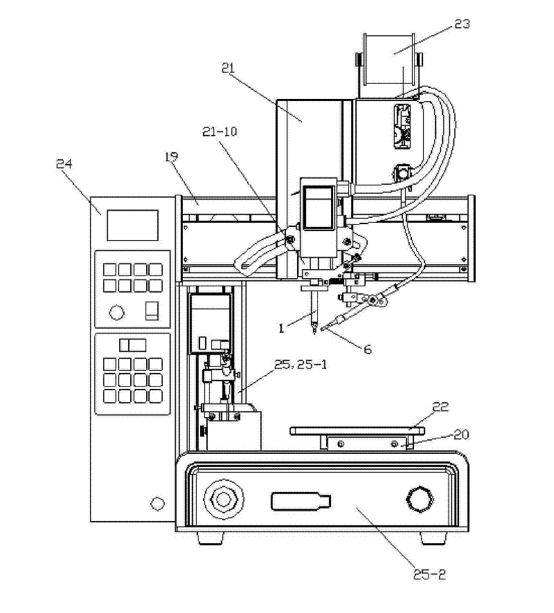
[0069] See figure 1 , the automatic soldering robot of the present embodiment comprises a soldering iron head 1, an X-axis module 19 for controlling movement in the left and right direction, a Y-axis module 20 for controlling the movement in the front-back direction, a Z-axis module 21 for controlling the movement in the up-down direction, and a load for placing workpieces to be welded. Plate 22, wire feeding mechanism 23 and electrical control box 24; X-axis module 19 is fixed on the column 25-1 upper end of frame 25, Y-axis module 20 is fixed on the base 25-2 of frame 25, Z-axis module 21 and The X-axis module 19 is slidingly connected, the wire feeding mechanism 23 is fixed on the Z-axis module 21, and the loading plate 22 is fixed on the Y-axis module 21; the soldering iron tip movement mechanism is fixed on the Z-axis module 21 through the Z-axis connecting block 21-1 , The tin wire precise positioning mechanism is fixed on the upper end of the soldering iron tip 1. The ...


PUM


Abstract

The invention relates to an automatic solder robot comprising a soldering bit, an X-axis module, a Y-axis module, a Z-axis module, a carrying board, a wire feeding mechanism and an electric control box as well as a soldering bit motion mechanism and an accurate solder wire positioning mechanism. The soldering bit motion mechanism comprises a moving device which is connected with the soldering bitand comprises a connecting block, an air cylinder, a sliding plate and a linear sliding rail; the connecting block is used for connecting the upper end of the soldering bit with the cylinder body of the air cylinder together and connected with the sliding plate which is glidingly connected with the linear sliding rail; a solder wire nozzle of the accurate solder wire positioning mechanism is connected with the connecting block through a connecting rod, the connecting block is connected with a connecting shaft which is fixedly connected with a deflection block and is in rotating connection with an elevation block, a clamping block is connected with the elevation block and fixed at the upper end of the soldering bit, a horizontal adjusting screw is in rotating connection with the deflectionblock, and the front end of the horizontal adjusting screw is glidingly connected with the elevation block. The invention can accurately solder melted tin solder in a needed position and improve the efficiency, the product quality consistency and stability.

Description

technical field [0001] The invention relates to an automatic soldering robot. Background technique [0002] Automatic soldering technology has attracted more and more attention because it can solve the low-quality and low-efficiency problems of manual soldering due to human factors. The soldering machine is mainly used for tinning on PCB boards with electronic components inserted Let the liquid tin stick to the insertion hole of the PCB board on the tin surface of the tin furnace, so that the electronic components can be soldered to the PCB board. Soldering machines mainly include immersion welding machines and wave soldering machines: 1. Immersion welding machines, which are about to fix the container for storing tin liquid, let the circuit board move downward, so that the welding surface reaches below the surface of the tin liquid, so as to achieve soldering the goal of. The disadvantage of this is that if the circuit board is moved up and down, it is prone to short circ...

Claims


Application Information

Patent Timeline
Patent Type & Authority Patents(China)
IPC IPC(8): B23K3/00B23K101/36H05K3/34
Inventor 李长峰曲东升闵继江许国华徐庆海孙岩查进傅成
Owner CHANGZHOU MINGSEAL ROBOT TECH CO LTD
Why Eureka
Try Eureka