Optical device and optical element thereof

A technology of optical elements and light, applied in the direction of optical elements, optical components, optics, etc., can solve the problems of decreased light transmittance, uncomfortable vision, difficult application, etc.

Inactive Publication Date: 2011-05-25
HONG FU JIN PRECISION IND (SHENZHEN) CO LTD +1
View PDF3 Cites 5 Cited by
  • Summary
  • Abstract
  • Description
  • Claims
  • Application Information

AI Technical Summary

Problems solved by technology

For example, reflected light from a water surface, glass surface or metal surface will contain polarized light, and this polarized reflected light will cause glare, making the observer visually uncomfortable and thus unable to see objects clearly
[0004] Since most of the polarized light that causes glare is X-type polarized light, in order to solve this problem, it is known that polymer materials are drawn into filaments and arranged in a direction to eliminate X-type polarized light to reduce glare. However, due to the lack of free electrons in polymer materials, the efficiency of eliminating electric field vibrations is poor, and a certain thickness must be used to achieve the effect of reducing glare. However, the increase in thickness will lead to a serious decrease in light transmittance, making this material more Difficult to apply to optical products

Method used


Image

  • Optical device and optical element thereof
  • Optical device and optical element thereof
  • Optical device and optical element thereof

Examples


Embodiment Construction

[0014] The optical device of the embodiment of the present invention will be described in detail below with reference to the accompanying drawings.

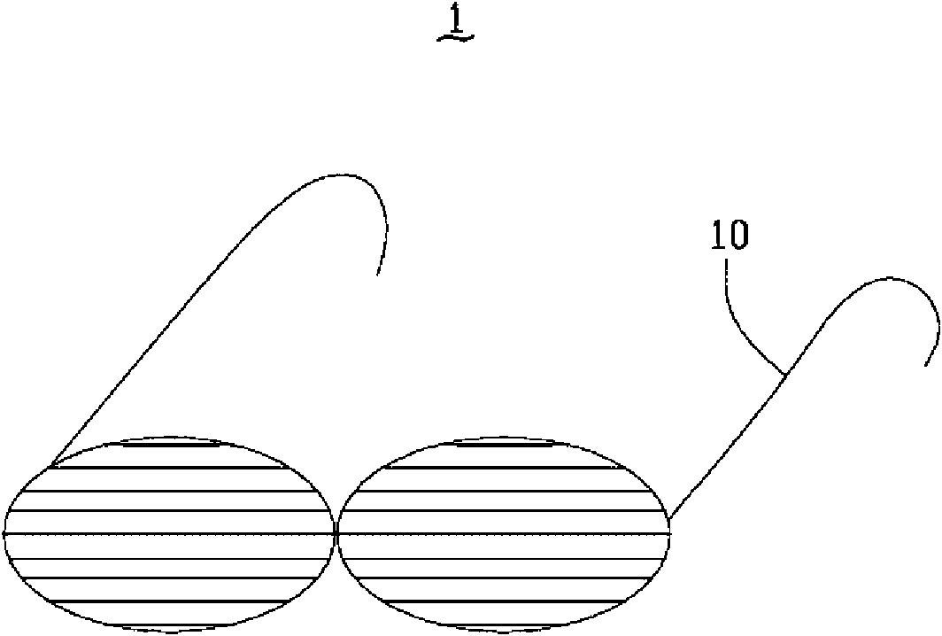
[0015] Please refer to figure 1 and figure 2 As shown, an optical device 1 according to a preferred embodiment includes a body 10 and an optical element 11 accommodated in the body 10 . The optical device 1 can be, for example, a pair of sunglasses, a camera, a video camera, a building glass or a car windshield. In this embodiment, the optical device 1 is described by taking sunglasses as an example. Here, the body 10 is a frame, and the optical element 11 is, for example, a lens frame disposed in the frame 10 .

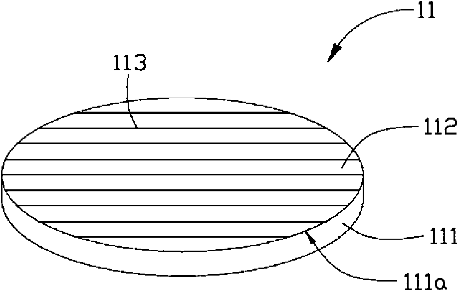
[0016] The optical element 11 includes a base body 111 and an anti-glare layer 112, and the base body 111 has a surface 111a. In this embodiment, the base 111 is a glass lens, however, the material of the base 111 is not limited thereto, it can also be a flexible base, for example: polyethylene terephthalate (PET ...


PUM

PropertyMeasurementUnit
thicknessaaaaaaaaaa

Abstract

The invention provides an optical element which comprises a substrate and an anti-glare layer, wherein the substrate has a surface, and light reflected by a smooth plane is incident on the surface of the substrate; and the anti-glare layer comprises a plurality of carbon nanotubes which are parallelly arranged on the surface of the substrate, and the length extension directions of the carbon nanotubes are parallel to a polarization direction of the light.

Description

technical field [0001] The invention relates to an optical device and an optical element thereof, in particular to an optical device based on carbon nanotubes and an optical element thereof. Background technique [0002] Light is a kind of electromagnetic wave, which is formed by the vibration of alternating electric field and magnetic field perpendicular to the direction of light propagation. The wave whose vibration direction is perpendicular to the direction of propagation is also called transverse wave. The vibration of the transverse wave is polar. Generally speaking, the polarity of light refers to the vibration direction of the light wave in the electric field. If the vibration direction of the light wave is asymmetric to the direction of light propagation, it is called polarized light. [0003] Generally, the vibration of natural light in all directions is uniformly distributed, which belongs to unpolarized light. However, when unpolarized light is incident on a smoo...

Claims


Application Information

Patent Timeline
Patent Type & Authority Applications(China)
IPC IPC(8): G02B1/11C01B31/00G02C7/10
CPCG02B2207/101G02B5/3058B82Y20/00
Inventor 魏朝沧陈杰良
Owner HONG FU JIN PRECISION IND (SHENZHEN) CO LTD
Why Eureka
Try Eureka