Optical cable splitting box

A fiber distribution box and optical cable technology, applied in the direction of fiber mechanical structure, etc., can solve the problems of unclear routing, low installation efficiency, inconvenient maintenance and operation, etc., and achieve the effect of flexible and convenient configuration, good sealing performance and strong versatility

Active Publication Date: 2012-08-29
CHANGZHOU TAIPING COMM SCI & TECH
View PDF0 Cites 0 Cited by
  • Summary
  • Abstract
  • Description
  • Claims
  • Application Information

AI Technical Summary

Problems solved by technology

[0004] 1. The security of the optical splitter is not high
The currently disclosed optical splitters all use optical splitter discs, and the optical splitters are installed on the lower part of the middle flap of the cabinet through the disc body. Because the optical splitter disc has no cover plate, it is inevitable that dust will enter the light. In the splitter, the optical fiber is physically damaged, resulting in a lack of protection for the optical fiber, and the use safety is not high
[0005] 2. The universality of the mounting bracket is poor
Since the splitter panel is installed on the cabinet through the mounting bracket, and the mounting brackets are all fixed structures, if you need to add adapters on the optical splitter, you must replace the mounting bracket, so the mounting bracket is not universal
[0006] 3. It is difficult to introduce and install the butterfly cable pigtail
However, the butterfly cable lead-in mechanism of the existing optical fiber distribution box is that a rubber plate with holes is installed on the inside of the box, and the butterfly cable passes through the hole on the rubber plate, and is connected to the butterfly cable by the elasticity of the rubber plate. Sealed, the butterfly cable introduced into the box is fixed with Hubble and the box, but because the lead butterfly cable pigtail cannot be threaded, it cannot be connected with the factory butterfly cable pigtail, and it also limits the butterfly cable. quantity
The other is that a cable inlet hole is provided on the box, and a fixing seat is provided inside the box. It can satisfy the threading of butterfly cable pigtails, and the number of butterfly cables is not limited, but there is also the problem that the sealing performance is greatly reduced, so it will cause direct damage to the components in the box and even optical passive devices, and affect the product. Quality, and there are also unclear routings, which brings inconvenience to maintenance operations
[0007] 4. It is inconvenient to dig out the optical cable
Since the cable inlet hole on the fiber optic cable distribution box is only provided with a closed hole on the box wall, and the fiber optic cable needs to be stripped and then fixed into the box, but it will not be possible in narrow corridors, weak electric wells and other spaces. Even in an open place, since the optical cable needs to be inserted into the cable hole after stripping, it not only increases the difficulty of construction, but also cannot fix the optical cable introduced into the box
[0008] 5. The internal wiring route is not clear, which may easily cause messy wiring for users, long construction period on site, and low installation efficiency

Method used


Image

  • Optical cable splitting box
  • Optical cable splitting box
  • Optical cable splitting box

Examples


Embodiment Construction

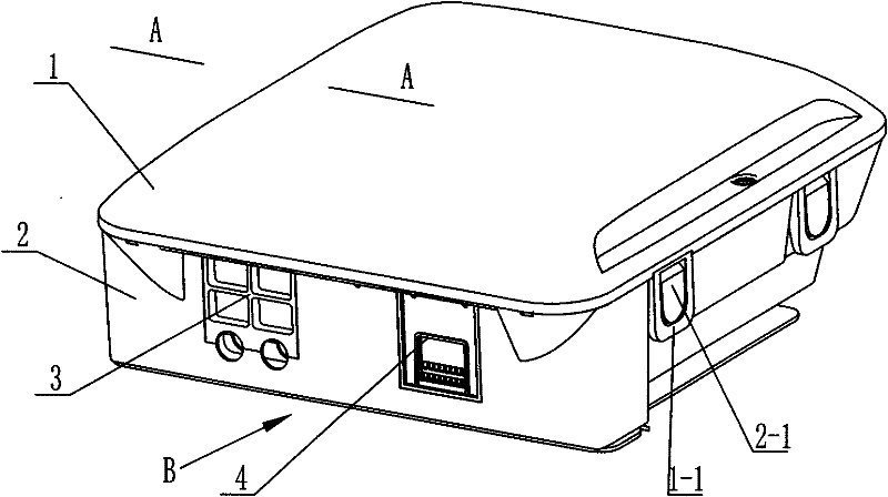
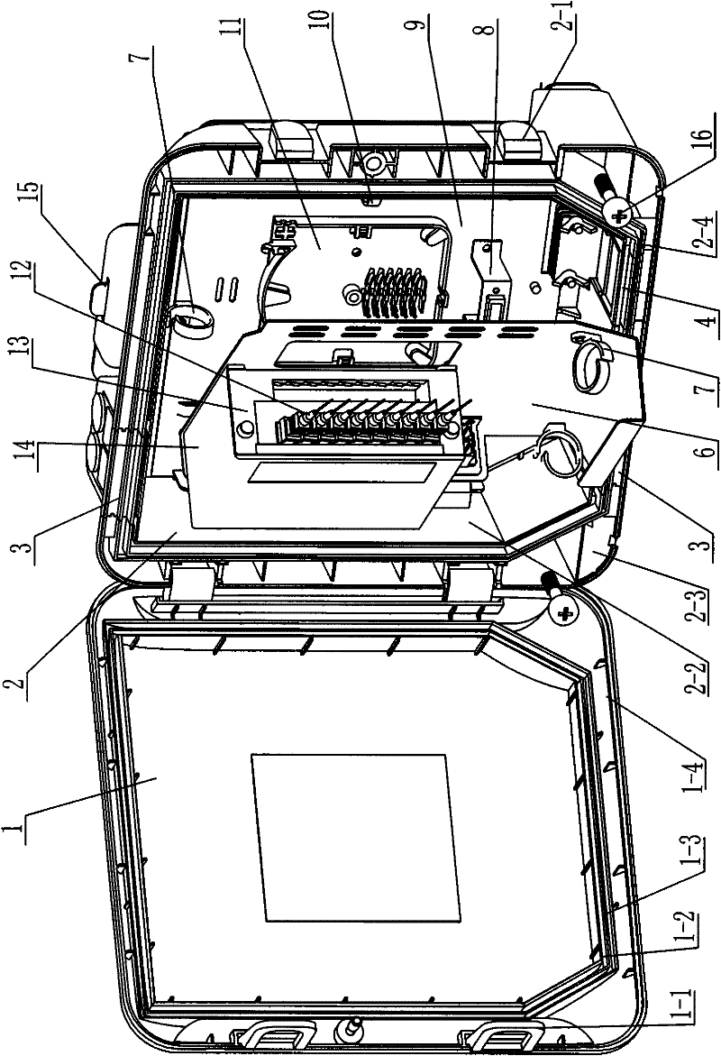
[0037] See Figure 1-12 As shown, the fiber distribution box of the present invention includes a box body 2, a box cover 1, a middle flap 6, a bottom plate 9, a splice tray 11, an optical splitter box 13, a mounting bracket 14 and a threading mechanism 4.

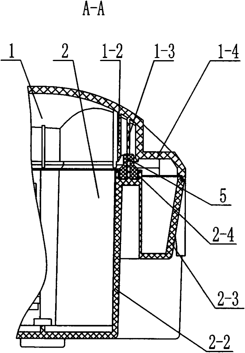
[0038] See Figure 1-7 Shown, box body 2 of the present invention and box cover 1 can adopt non-metallic high-strength material to make, and the box wall 2-2 periphery of box body 2 has to be connected with box wall 2-2 peripheral wall 2-3, and peripheral wall 2 A plurality of reinforcing ribs are connected between -3 and the box wall 2-2 and between the peripheral wall 2-3, and the top of the box wall 2-2 of the box body 2 is provided with a mountain-shaped annular sealing groove 2-4, and the peripheral wall 2 -3 The top is provided with a lower stop, and the cover wall of the box cover 1 is also provided with an outer side wall 1-4 connected with the cover wall. The box cover 1 is located on the inner side of the cover w...


PUM


Abstract

The invention relates to an optical cable splitting box. The peripheral wall of a box body is hinged with one side of the outside wall of a box cover through a hinge; two press block gaps and sliding plate gaps which are opposite to each other are reserved on the box body; two optical cable pressing blocks of which the bottoms are provided with upper arc-shaped grooves are respectively plugged inthe press block gaps to form optical cable holes; threading sliding plates are plugged in the sliding plate gaps; a pressing plate and more than one fixing seat are plugged in vertical guide rails ofthe threading sliding plates in turn from the top to the bottom; an L-shaped bottom plate is arranged on a box bottom plate of the box body; a supporting seat and a welding disk are arranged on the bottom plate; the bottom plate is provided with more than two cable locking rings as well as optical cable fasteners and a grounding bolt; one side of an intermediate overturning plate is rotatably connected with the bottom plate through a pin shaft; a mounting bracket, a tail optical fiber parking seat and a cable locking ring are arranged on the upper part of the intermediate overturning plate; and an optical branching device box is plugged in the mounting bracket or / and an intermediate bearing support through longitudinal guide plates on the two sides. The optical cable splitting box has thecharacteristics that: the structure is reasonable, the internal wiring route is clear, the optical cable splitting box is convenient to operate, and the optical branching device is flexible to configure.

Description

technical field [0001] The invention relates to an optical fiber distribution box and belongs to the technical field of optical communication equipment. Background technique [0002] With the mature application of passive optical network (PON) technology, the rapid development of new services including IP video and cloud computing, and the progress of society, people's continuous demand for high-bandwidth services such as high-definition interactive network television (IPTV) and video surveillance The communication industry has realized that fiber-to-the-building (FTTB), especially fiber-to-the-node (FTTN), is difficult to meet the needs of long-term business development. etc. are facing new upgrade requirements, so fiber-to-the-home (FTTH) will also become a final form of optical fiber access network development. In the construction and deployment of fiber-to-the-home, the ODN (Optical Distribution Network, optical distribution network) product solution affects the quality...

Claims


Application Information

Patent Timeline
Patent Type & Authority Patents(China)
IPC IPC(8): G02B6/44
Inventor 陈开卓王立军任献忠石新根吴锦辉王绪章
Owner CHANGZHOU TAIPING COMM SCI & TECH
Why Eureka
Try Eureka