System and method for self-checking of set-top box

A set-top box and log technology, applied in the transmission system, digital transmission system, data exchange through path configuration, etc., can solve the problems of increasing maintenance time, delaying the normal use of users, and increasing the maintenance cost of set-top box manufacturers, so as to increase satisfaction, The effect of saving maintenance costs

Inactive Publication Date: 2011-05-25
SUN YAT SEN UNIV
5 Cites 27 Cited by

AI-Extracted Technical Summary

Problems solved by technology

In this way, it will not only increase the maintenance cost of the set-top box manu...

Abstract

The embodiment of the invention discloses a system for self-checking of a set-top box. The system comprises the set-top box, a home gateway and a maintenance server, wherein the set-top box is used for automatically detecting hardware of the set-top box, sending out an alarm if detecting that certain hardware fails, reporting to a user through a display, generating a test log and transmitting the test log to a maintenance server through the home gateway; the home gateway is used for receiving the test log transmitted by the set-top box and transmitting the test log to the maintenance server; and the maintenance server is used for receiving the test log transmitted by the home gateway and displays the test log to the user. By implementing the system, the maintenance personnel do not need to solve some common problems in person, so that the satisfaction of a user is improved while the maintenance cost of a manufacturer is saved.

Application Domain

Technology Topic

Image

  • System and method for self-checking of set-top box
  • System and method for self-checking of set-top box
  • System and method for self-checking of set-top box

Examples

  • Experimental program(1)

Example Embodiment

[0021] The following will clearly and completely describe the technical solutions in the embodiments of the present invention with reference to the accompanying drawings in the embodiments of the present invention. Obviously, the described embodiments are only some, not all, embodiments of the present invention. Based on the embodiments of the present invention, all other embodiments obtained by persons of ordinary skill in the art without creative efforts fall within the protection scope of the present invention.
[0022] The present invention will be further described below in conjunction with the accompanying drawings and embodiments.
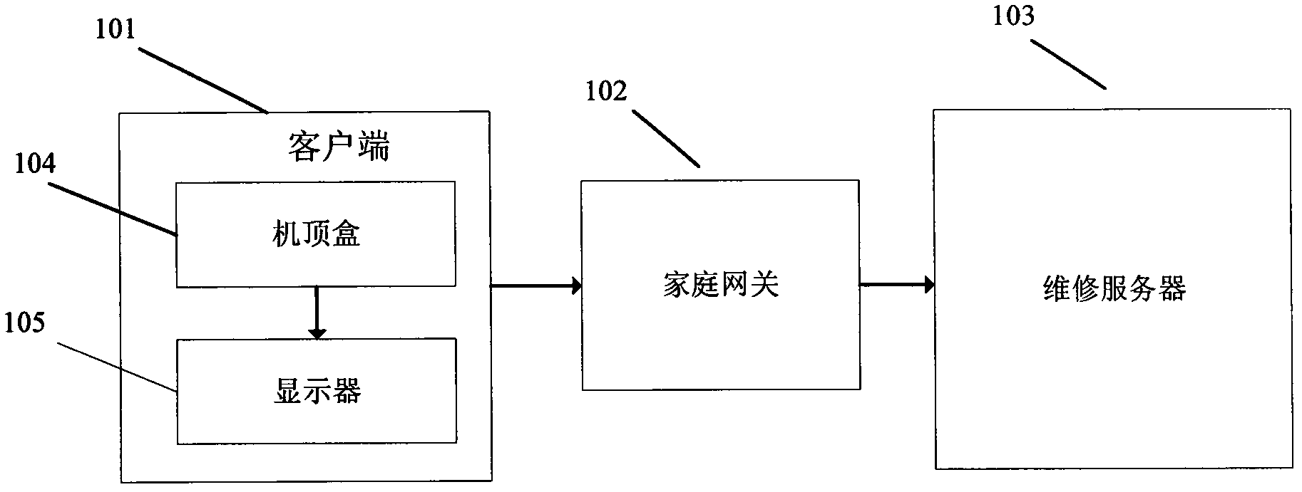
[0023] A system for self-testing of a set-top box in an embodiment of the present invention includes: a set-top box, which is used to automatically detect the hardware of the set-top box; The logs are sent to the maintenance server through the home gateway; the home gateway is used to receive the test logs sent by the set-top box and send the test logs to the maintenance server; the maintenance server is used to receive the test logs sent by the home gateway and display the test logs to the user.
[0024] Specific as figure 1 Shown is a structural diagram of a set-top box automatic detection system of the present invention. The system includes: a client 101 , a home gateway 102 , and a maintenance server 103 .
[0025] Client 101: After the customer turns on the machine each time, it automatically detects hardware such as the set-top box motherboard, display, memory, power supply, etc., if a certain hardware is detected to be faulty. An alarm is sent to report the user through the display, a test log is generated, and the test log is sent to the maintenance server through the home gateway. The client 101 includes a two-way digital set-top box 104 and a display 105 .
[0026] Two-way digital set-top box 104: the self-test part includes:
[0027] Communication unit 203: used for data transmission between the above-mentioned units. When the analysis unit is working, it is responsible for querying the hardware status and fault model database from the storage unit for analysis and comparison. And responsible for transmitting the generated test log to the display 201 and the home gateway 202 .
[0028] Storage unit 204: for storing hardware of the set-top box such as a motherboard. monitor. Standard states for memory, power supplies, etc., and a failure model database.
[0029] Monitoring unit 206: used to monitor the hardware of the set-top box such as the motherboard after the set-top box is turned on. monitor. Monitor the status of memory, power supply, etc.
[0030] Analysis unit 205: used for comparing and analyzing the hardware state of the set-top box detected by the monitoring unit with the standard state in the storage unit to detect whether the hardware is faulty, and if there is a fault, compare it with the fault model library to analyze the cause of the fault. Find the cause of the failure to generate a test log, display it to the customer through the monitor, and send it to the set-top box manufacturer.
[0031] Display 105: connected to the set-top box at the client end, can be a digital TV or any display device, can accept the test log sent by the communication unit 203, and display it to the user, for the user to analyze the cause of the set-top box failure.
[0032] Home gateway 102: stores the address of the maintenance server, searches for the maintenance server according to the storage address after receiving the test log sent by the communication unit, and is responsible for sending the test log to the maintenance server.
[0033] Maintenance server 103: to receive the test log sent by the home gateway and display it to the maintenance personnel.
[0034] In order to further understand the operation process of the present invention, below in conjunction with image 3 It is a step diagram of a set-top box automatic detection system of the present invention for illustration:
[0035] The manufacturer of the set-top box hit by this method stores the hardware standard status value and the inspection order of each hardware in the set-top box when it leaves the factory.
[0036] As shown in steps 301 and 302, the user turns on the power normally, and the set-top box automatically enters the hardware detection program.
[0037] As shown in step 303, the set-top box checks the hardware in the first order after powering on. Start to check the first hardware, the selection of the hardware is subject to the hardware check sequence set at the factory.
[0038] As shown in steps 304, 305, and 306, the set-top box checks whether the hardware is faulty, and if a fault is found, a fault is reported, and the fault is analyzed and recorded in the test log to judge whether the detected hardware is the final inspection hardware; if the hardware is checked If there is no fault, then go directly to step 306 to check whether it is the final detection hardware.
[0039] As shown in step 307, if the detection in step 306 is not the final hardware detection, continue to the detection of the next hardware.
[0040] As shown in step 308, if the detection in step 306 is the final detection of hardware, the detection is completed, and the generated test logs are sent to the client display and the home gateway respectively. If there is no failure that causes the set-top box to be paralyzed, then enter the normal boot procedure.
[0041] By implementing the embodiment of the present invention, it is no longer necessary for maintenance personnel to come to the door in person for some common problems, thus saving the maintenance cost of the manufacturer and increasing user satisfaction.
[0042] It should be noted that the information interaction and execution process between the above-mentioned system and each unit in the system are based on the same idea as the method embodiment of the present invention, and the specific content can refer to the description in the method embodiment of the present invention. Here No longer.
[0043] Those of ordinary skill in the art can understand that all or part of the steps in the various methods of the above embodiments can be completed by instructing related hardware through a program, and the program can be stored in a computer-readable storage medium, and the storage medium can include: only Read memory (ROM, Read Only Memory), random access memory (RAM, Random Access Memory), magnetic disk or optical disk, etc.
[0044] The system and method for self-testing of a set-top box provided by the embodiment of the present invention above, the principle and implementation of the present invention are explained by using specific examples in this paper, and the description of the above embodiment is only used to help understand the method of the present invention and its core idea; at the same time, for those of ordinary skill in the art, according to the idea of ​​the present invention, there will be changes in the specific implementation and application scope. limits.

PUM

no PUM

Description & Claims & Application Information

We can also present the details of the Description, Claims and Application information to help users get a comprehensive understanding of the technical details of the patent, such as background art, summary of invention, brief description of drawings, description of embodiments, and other original content. On the other hand, users can also determine the specific scope of protection of the technology through the list of claims; as well as understand the changes in the life cycle of the technology with the presentation of the patent timeline. Login to view more.

Similar technology patents

Adjusting mechanism of electrically tunable antenna

InactiveCN106252883AQuick and easy installation and removalReduce maintenance costsAntennasElectric machineRisk stroke
Owner:MOBILE ANTENNA TECH SHENZHEN +2

Classification and recommendation of technical efficacy words

  • Reduce maintenance costs
  • Improve satisfaction

Screen font zooming method and terminal unit

InactiveCN101271678AGood visionImprove satisfactionCathode-ray tube indicatorsMusic playerTerminal unit
Owner:HUAWEI DEVICE (SHENZHEN) CO LTD
Why Eureka
Try Eureka