

Rotary mechanism for machine tool
A technology of rotating mechanism and power transmission mechanism, which is applied in the direction of driving devices, mechanical equipment, metal processing machinery parts, etc., which can solve the problems of reducing the accuracy of stop positioning and difficulty in shortening the processing operation time, and achieve the effect of improving the rotation speed
- Summary
- Abstract
- Description
- Claims
- Application Information
AI Technical Summary
Problems solved by technology
Method used
Image

Examples
no. 1 approach
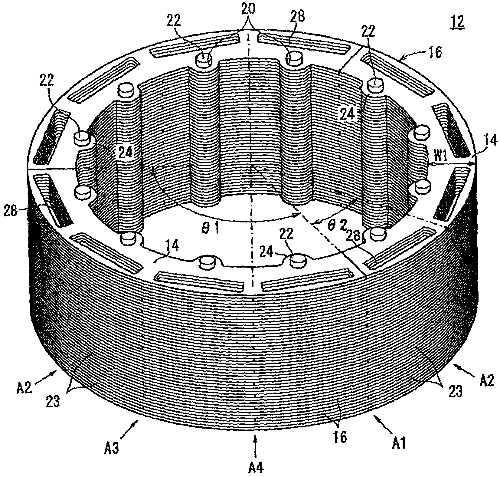
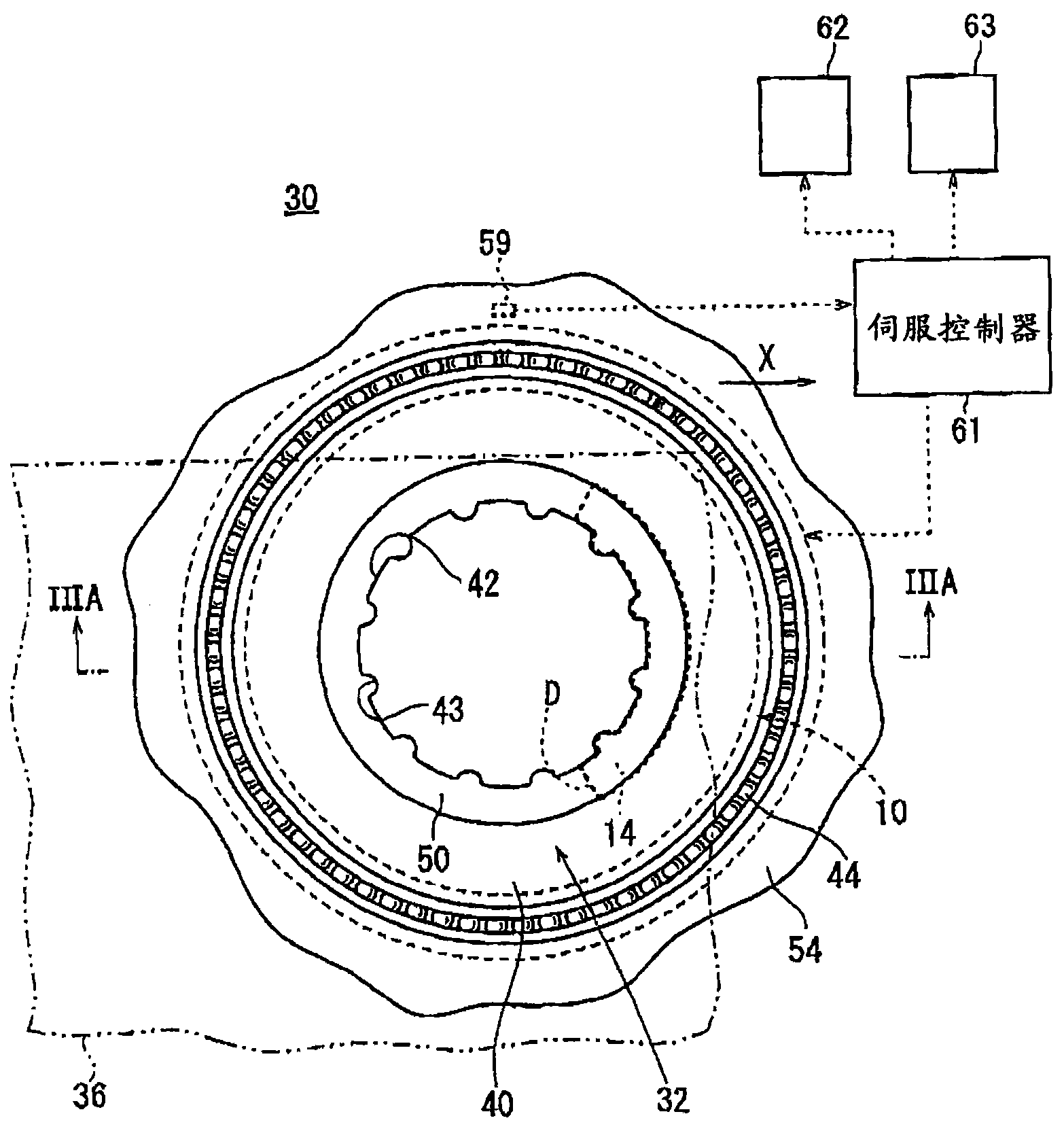
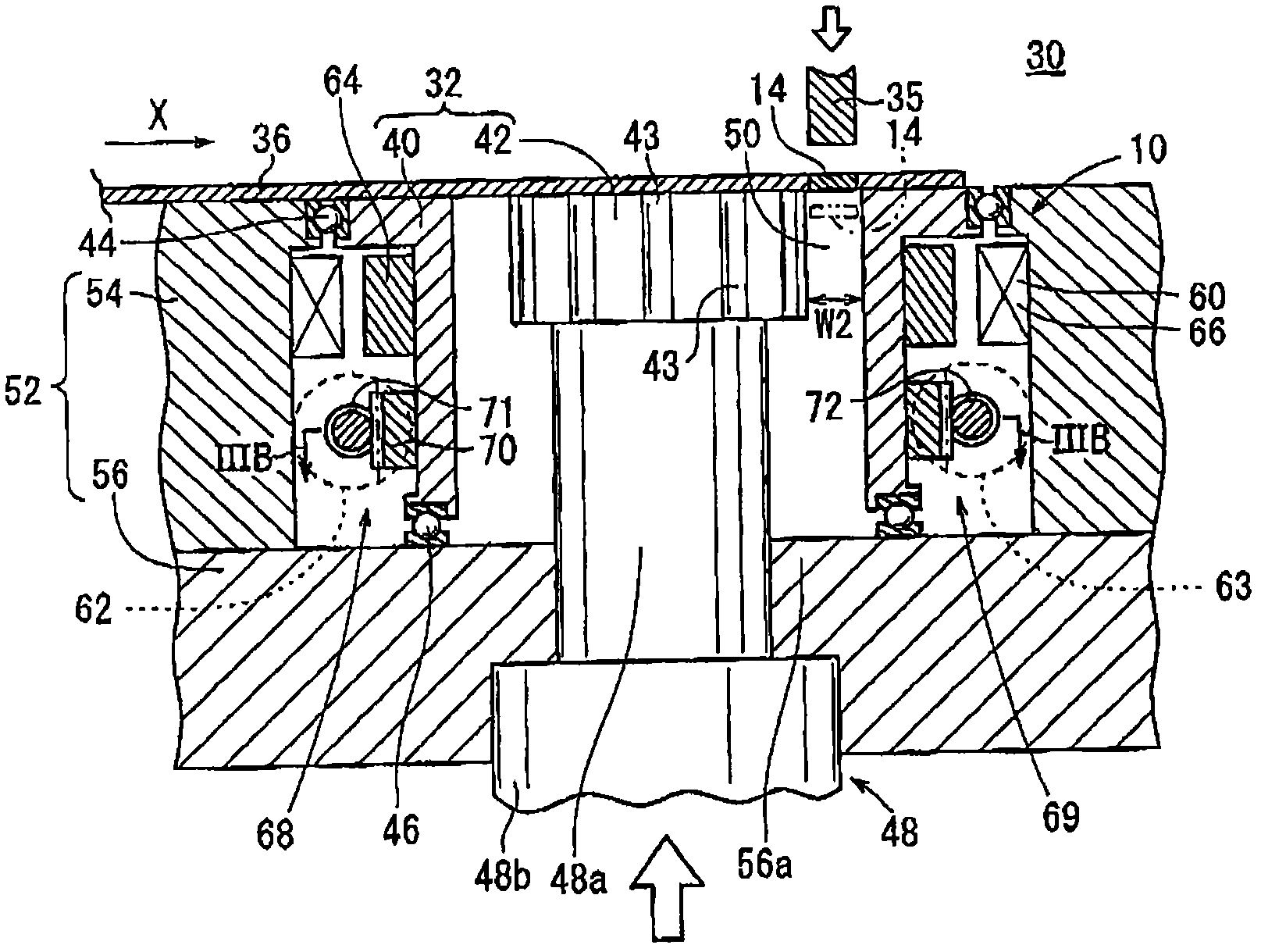
[0051] figure 2 It is a plan view of the stacking apparatus 30 (press die assembly) equipped with the driving device (rotation mechanism) 10 according to the first embodiment, and part is omitted. Such as figure 2 As shown, the stacking apparatus 30 includes a rotating stack receiving die assembly 32 (workpiece support device, die assembly) for supporting the separated core plates 14 to be stacked, a drive device 10 for rotatably driving the rotating stack receiving die assembly 32 , and the stamping machine 35 ( Figure 3A ).
[0052] After the separated core panels 14 have been punched out from the sheet material 36 , the separated core panels 14 are returned to the corresponding punching sections, and are supplied to the stacking device 30 in a state constituting the partial sheet material 36 . In the sheet material 36, the divided core plates 14 formed in this way are arranged at a predetermined distance in the conveying direction (direction of arrow X). When the sep...
no. 2 approach
[0080] Figure 4 is a schematic cross-sectional view showing the structure of a drive device (rotation mechanism) 10a for a machine tool and its peripheral components according to a second embodiment of the present invention. In the stacking device 30a equipped with the driving device 10a according to the second embodiment, the structural elements that are the same as those of the stacking device 30 equipped with the driving device 10 according to the first embodiment or have the same function and effect are assigned the same reference numerals to indicate, and a detailed description of these elements is omitted.
[0081] The driving device 10a according to the second embodiment includes a first motor 76 and a second motor 78, the first motor 76 is mainly responsible for rotatably driving and positioning the stack receiving mold assembly 32, and the second motor 78 is mainly responsible for rotatably driving the rotation The stack receives the mold assembly 32 .
[0082] The...
no. 3 approach
[0091] Figure 5A is a schematic cross-sectional view showing the structure of a driving device (rotation mechanism) 10b for a machine tool (hereinafter simply referred to as "driving device") and its peripheral components according to a third embodiment of the present invention. Figure 5B for along Figure 5A A cross-sectional view taken along the line VB-VB. In the stacking device 30b equipped with the driving device 10b according to the third embodiment, the structural elements that are the same as those of the stacking device 30 equipped with the driving device 10 according to the first embodiment or have the same function and effect are assigned the same reference numerals to indicate, and a detailed description of these elements is omitted.
[0092] The driving device 10b according to the third embodiment includes a first motor 80 and a second motor 82, the first motor 80 is mainly responsible for rotatably driving and positioning the stack receiving mold assembly 32,...
PUM
 Abstract
Description
Claims
Application Information