A clamping die upsetting machine and its working method

A technology of upsetting forging machine and die-clamping seat, which is applied to upsetting forging presses, swaging presses, forging/pressing/hammering machines, etc. The effect of improving work efficiency, improving upsetting efficiency and simplifying structure

Inactive Publication Date: 2018-04-24
DONGGUAN SHIXI INTELLIGENT MACHINE MFG
View PDF6 Cites 0 Cited by
  • Summary
  • Abstract
  • Description
  • Claims
  • Application Information

AI Technical Summary

Problems solved by technology

These two types of upsetting machines mostly use wire rods as raw materials for upsetting at present. Therefore, before upsetting, the wire rods must be cut into blanks according to the size requirements of the formed parts. In order to realize this process, upsetting machines need separate The installation of material cutting device and material clamping and conveying device makes the structure of the whole heading machine complex, and requires high cooperation among cutting material, upsetting and ejection, and it is difficult to realize high-speed upsetting, and debugging is particularly troublesome
[0006] For the multi-mode and multi-blow upsetting machine, the dies are arranged horizontally, the multiple dies are fixed, and the multiple punches only move in one direction for the upsetting section. Since the dies or punches will not move in translation, therefore, The billet can only be transferred by clamp movement, and the billet is only upset once in the die
[0007] In addition, for the existing upsetting machine, the die is basically an integral structure, and for the formed die, the cavity is determined. Therefore, on the premise of not changing the die, basically only one kind of molding can be formed. Upsetting parts, at the same time, it is also impossible to upsetting complex shaped parts

Method used


Image

  • A clamping die upsetting machine and its working method
  • A clamping die upsetting machine and its working method
  • A clamping die upsetting machine and its working method

Examples


Embodiment 1

[0066] In this embodiment, the specific structure and working method of the die-closing upsetting machine are explained by using the one-touch die-closing upsetting machine.

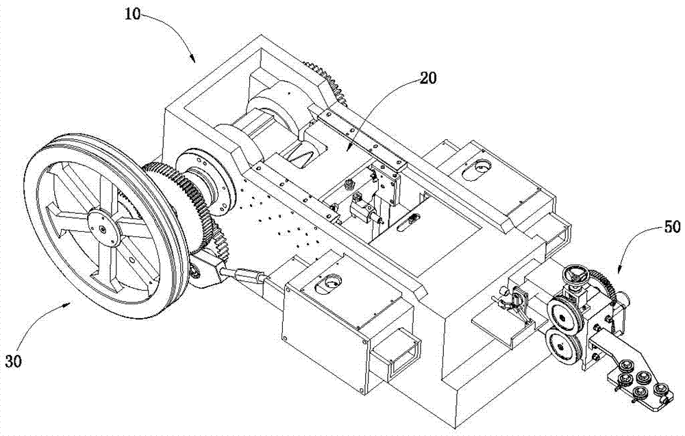
[0067] Such as figure 1 , figure 2 with image 3 As shown, the clamping and upsetting machine includes a body 10, a punch assembly 20 mounted on the body 10, a punch assembly driving mechanism 30 that drives the movement of the punch assembly 20, a feeding mechanism 50 and a mold clamping assembly provided on the body 10 90.

[0068] Such as figure 2 with image 3 As shown, the machine body 10 includes a frame 11, a base body 12, and a cover 13; the frame 11 includes a frame body 111 and a frame base 112, and the frame base 112 includes a base body 1122 and end plates. 1123, the base body 1122 has an accommodating cavity 1121, the two ends of the accommodating cavity 1121 have openings 11211, and the end plate 1123 is fixed on the base body 1122 located at the opening. In this embodiment, both ends of the ...

Embodiment 2

[0099] In this embodiment, the specific structure and working method of the die-closing upsetting machine are explained by using the one-touch die-closing upsetting machine.

[0100] Such as figure 1 , figure 2 with image 3 As shown, the clamping and upsetting machine includes a body 10, a punch assembly 20 mounted on the body 10, a punch assembly driving mechanism 30 that drives the movement of the punch assembly 20, a feeding mechanism 50 and a mold clamping assembly provided on the body 10 90.

[0101] Such as figure 2 with image 3 As shown, the machine body 10 includes a frame 11, a base body 12, and a cover 13; the frame 11 includes a frame body 111 and a frame base 112, and the frame base 112 includes a base body 1122 and end plates. 1123, the base body 1122 has an accommodating cavity 1121, the two ends of the accommodating cavity 1121 have openings 11211, and the end plate 1123 is fixed on the base body 1122 located at the opening. In this embodiment, both ends of the ...

Embodiment 3

[0153] In this embodiment, the specific structure and working method of the die-closing upsetting machine are explained by using the one-touch die-closing upsetting machine.

[0154] Such as figure 1 , figure 2 with image 3 As shown, the clamping and upsetting machine includes a body 10, a punch assembly 20 mounted on the body 10, a punch assembly driving mechanism 30 that drives the movement of the punch assembly 20, a feeding mechanism 50 and a mold clamping assembly provided on the body 10 90.

[0155] Such as figure 2 with image 3 As shown, the machine body 10 includes a frame 11, a base body 12, and a cover 13; the frame 11 includes a frame body 111 and a frame base 112, and the frame base 112 includes a base body 1122 and end plates. 1123, the base body 1122 has an accommodating cavity 1121, the two ends of the accommodating cavity 1121 have openings 11211, and the end plate 1123 is fixed on the base body 1122 located at the opening. In this embodiment, both ends of the ...


PUM


Abstract

Provided is a clamp die upsetting machine, comprising a machine body (1), a punching die assembly (3), a punching die assembly drive mechanism, a feed mechanism, and a cropping cover (37); a clamp die assembly (39) is disposed on the machine body; the clamp die assembly (39) comprises a first clamp die base (55) and a second clamp die base (56); a first mounting space (57) is disposed at the side face, adjacent to the second clamp die base (56), of the first clamp die base (55); a second mounting space (58) is disposed at the side face, adjacent to the first clamp die base (55), of the second clamp die base (56); also disposed are a first clamp die drive mechanism for driving the first clamp die (55) in translational motion, and a second clamp die drive mechanism for driving the second clamp die (56) in translational motion; the working method is: the translational motion of the clamp die assembly is used to achieve displacement whole-circle cropping and workstation-piece material delivery; then, upsetting is performed; thus the needs for a separate cropping mechanism and material clamping and blank delivery mechanism are eliminated, and the functions of clamp die cropping, clamp die upsetting, and clamping are achieved.

Description

Technical field [0001] The invention relates to an upsetting machine and its working method. Background technique [0002] The upsetting machine is a device that uses the back and forth movement of a large slider to upset the blank in the main die through a punch. [0003] The upsetting machine is mainly composed of a machine body, a punch assembly, a punch assembly drive mechanism, a main die, an ejection mechanism, a feeding mechanism and a cutting mechanism. [0004] In the traditional upsetting machine, the punch assembly and the die included in the main die are fixed on the corresponding body. The upsetting machine with this structure has many mechanical mechanisms, complex structures, many failures, difficult operations, and low upsetting efficiency. , Feeding and discharging are both troublesome. [0005] At present, the one-die two-punch forging machine and the multi-die and multi-punch forging machine that realize the shift between the forging stations through the lifting mo...

Claims


Application Information

Patent Timeline
Patent Type & Authority Patents(China)
IPC IPC(8): B21F5/00B21F11/00
CPCB21J9/06B21J13/03B21J13/04
Inventor 杨东佐
Owner DONGGUAN SHIXI INTELLIGENT MACHINE MFG
Why Eureka
Try Eureka