
Laser granulometer with multiple sample cells

A laser particle size analyzer and multi-sample technology, applied in particle size analysis, scientific instruments, particle and sedimentation analysis, etc., can solve problems such as complex structures

Inactive Publication Date: 2011-06-01
UNIV OF SHANGHAI FOR SCI & TECH
View PDF6 Cites 7 Cited by
  • Summary
  • Abstract
  • Description
  • Claims
  • Application Information

AI Technical Summary

Problems solved by technology

[0005] The object of the present invention is to overcome the disadvantages of expanding the particle size measurement range of the laser particle size analyzer in the prior art, but the structure is relatively complicated, and to provide a method that can expand the particle size measurement A multi-sample cell laser particle size analyzer with a wide range and a simple structure

Method used


Image

  • Laser granulometer with multiple sample cells
  • Laser granulometer with multiple sample cells
  • Laser granulometer with multiple sample cells

Examples


Embodiment 1

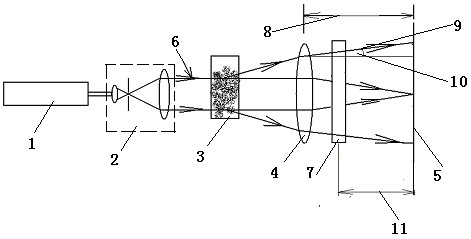
[0024] Depend on figure 2 As shown, when the measured particle size is relatively large, the particle sample is put into the sample cell 3, the laser beam 6 is incident on the particle sample, and the scattered light signal 9 is received by the receiving lens 4 and then received by the photodetector 5. Due to the larger particle size, the scattered light signal 9 is relatively concentrated at a smaller forward scattering angle 10 . A receiving lens 4 with a longer focal length 8 can be used to measure a finer spatial distribution of scattered light.

Embodiment 2

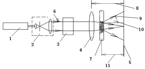
[0026] Contrary to example 1, in this embodiment, by image 3 As shown, the measured particle size is small, the particle sample is put into the sample cell 7 , the converged laser beam 6 is incident on the particle sample, and the scattered light signal 9 is received by the photodetector 5 . Since the equivalent focal length 11 is relatively small, when the same photodetector 5 as that in Embodiment 1 is used, scattered light signals in a larger angle can be measured, which reduces the lower limit of measurement.

Embodiment 3

[0028] Depend on Figure 4 As shown, since the focal length of the lens is fixed in the inverted Fourier transform optical path, the position of the sample cell behind the receiving lens can be determined according to the binning of different particle sizes. Therefore, if the lower limit of measurement is to be further lowered, a sample cell 12 can be arranged at a relatively short distance from the photodetector 5 behind the receiving lens 4, and when measuring the particle size of medium-sized particles, the sample can be placed behind the lens and away from the photodetector 5. In the sample pool 7 at a far distance from the detector. When measuring the particle size of large particles, the particle sample is put into the sample cell 3 in front of the receiving lens 4 .

[0029] In this embodiment, the particle size of the particles to be measured is smaller than that in Embodiment 2. The particle sample is placed in the sample cell 12 , the converged laser beam 5 is incid...


PUM


Abstract

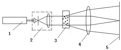
The invention discloses a laser granulometer with multiple sample cells which sequentially comprises a laser, a beam expander, sample cells, a receiving lens and an optical detector from front to back. The multi-sample cell laser granulometer disclosed by the invention is characterized in that sample cells are arranged in front and back of the receiving lens, and the optical detector is arranged on the focal plane of the lens; when large-size particles are measured, sample particles are put on the sample cell in front of the receiving lens so as to obtain the size of the largest particle and then obtain the measurement upper limit of the laser granulometer; and when small-size particles are measured, sample particles are put on the sample cell at the back of the receiving lens so as to obtain the measurement lower limit of the laser granulometer. The multi-sample cell laser granulometer disclosed by the invention has the beneficial effects that through adopting a technical scheme of multi-sample cells, the measurement upper and lower limits of the laser granulometer are expanded by using a simple structure.

Description

technical field [0001] The invention relates to a particle size measuring device of a laser particle size analyzer, in particular to a laser particle size analyzer with multiple sample pools. Background technique [0002] The laser particle size analyzer has been widely used in many fields. Its basic principle is that when a laser beam is incident on the particle sample to be measured, due to the scattering effect, the incident light will deviate from the original incident direction and scatter in all directions. The spatial distribution of light scattering is related to the size of the particles. When the particles are small, the forward scattered light is relatively weak, and when the particles are large, the forward scattered light is relatively strong. The laser particle size analyzer uses this principle to measure the distribution of scattered light in different directions, and then obtains the particle size distribution of the measured particles according to the light...

Claims


Application Information

Patent Timeline
IPC IPC(8): G01N15/02
Inventor 蔡小舒苏明旭
Owner UNIV OF SHANGHAI FOR SCI & TECH
Learn More