Particle-size measuring instrument
A measuring instrument and particle technology, applied in the direction of measuring device, particle size analysis, particle and sedimentation analysis, etc., can solve the problems of undetectable, small Brownian motion, etc., achieve the effect of expanding the structure and meeting the requirements of wide range particle size distribution measurement
- Summary
- Abstract
- Description
- Claims
- Application Information
AI Technical Summary
Problems solved by technology
Method used
Image
Examples
Embodiment 1
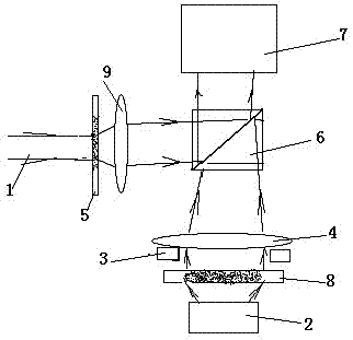
[0029] A multi-method fusion particle size analyzer, consisting of figure 1 As shown, the particle size analyzer consists of a laser light source 1, a non-monochromatic lighting source (2, 3), a microscope objective lens 4, a half-transparent mirror 6, an area array digital camera or video camera 7, and a sample cell (8, 5) Combined with the lens 9 to form a two-light path structure, one path is that the light emitted from the first non-monochromatic illumination source 2 irradiates the sample in the first sample pool 8, and the first sample pool 8 is located on the observation surface of the microscope objective lens 4 , the microscopic objective lens 4 passes the enlarged image to the area array digital camera or video camera 7 through the half-transparent mirror 6; The enlarged image passes through the half mirror 6 to the area array digital camera or video camera 7;
[0030] When measuring by the image method, the first non-monochromatic illumination light source 2 place...
Embodiment 2
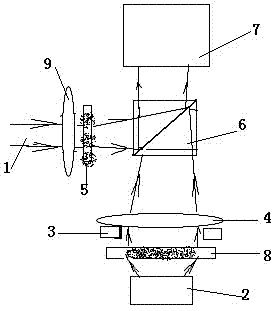
[0034] like figure 2 As shown, in this embodiment, the second sample cell 5 for light scattering measurement is located between the lens 9 and the half mirror 6 . Others are the same as embodiment 1. Such an optical path arrangement can reduce the volume of the instrument, and when the static light scattering method is used to measure particles, larger particles can be measured.
Embodiment 3
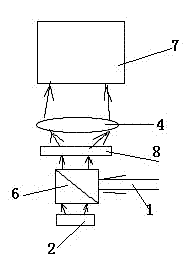
[0036] like image 3 As shown, in this embodiment, the sample cell is a sample cell 8, the half-mirror 6 is arranged below the sample cell 8, and the laser light source 1 and the non-monochromatic illumination light source 2 are respectively arranged on the half-mirror On both sides of 6, only one microscopic objective lens 4 is used, and the image of the particles and the scattered light signal are all received by the area array digital camera or video camera 7 to realize image measurement, static light scattering measurement and dynamic light scattering measurement.
[0037] In the above embodiments, light emitting diodes or light bulbs are used as non-monochromatic lighting sources. Area scan digital cameras are CCD or CMOS digital cameras.
PUM
 Abstract
Description
Claims
Application Information
 - R&D
- Intellectual Property
- Life Sciences
- Materials
- Tech Scout
- Unparalleled Data Quality
- Higher Quality Content
- 60% Fewer Hallucinations
Browse by: Latest US Patents, China's latest patents, Technical Efficacy Thesaurus, Application Domain, Technology Topic, Popular Technical Reports.
© 2025 PatSnap. All rights reserved.Legal|Privacy policy|Modern Slavery Act Transparency Statement|Sitemap|About US| Contact US: help@patsnap.com


