Multi-method combined particle size analyzer

A particle size analyzer and multi-method technology, applied in the field of particle size analyzers, can solve the problems of undetectable, small Brownian motion, etc., and achieve the effect of expanding the structure and meeting the requirements of wide-range particle size distribution measurement

Inactive Publication Date: 2011-06-15
UNIV OF SHANGHAI FOR SCI & TECH
View PDF4 Cites 19 Cited by
  • Summary
  • Abstract
  • Description
  • Claims
  • Application Information

AI Technical Summary

Problems solved by technology

However, when the particles are larger, the Brownian motion is too small to be detected, so the particle size can no longer be measured by this method

Method used


Image

  • Multi-method combined particle size analyzer
  • Multi-method combined particle size analyzer
  • Multi-method combined particle size analyzer

Examples


Embodiment 1

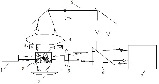
[0031] A multi-method fusion particle size analyzer, consisting of figure 1 As shown, the particle size analyzer consists of a laser light source 1, a first lighting source 2, a second lighting source 3, a microscope objective lens 4, a Dove prism 5, a half mirror 6, an area array digital camera or video camera 7, a sample The pool 8 and the lens 9 are combined into two light path structures, one path is that the light emitted from the illumination source 2 irradiates the sample in the sample pool 8, and the sample pool 8 is located on the observation surface of the microscopic objective lens 4, and the microscopic objective lens 4 will magnify the image After passing through the dove prism 5 and then through the semi-transparent mirror 6 to the area array digital camera or video camera 7; the other way is that the light emitted by the laser light source 1 is irradiated on the sample in the sample pool 8, and the lens 9 passes the enlarged image through the semi-transparent mi...

Embodiment 2

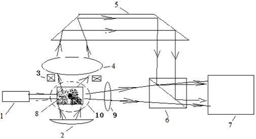
[0036] In Example 1, both static light scattering and dynamic light scattering measure forward scattered light. Because dynamic light scattering measures nanometer to submicron particles, the dynamic scattered light intensity of these tiny particles is relatively weak, but the scattered light intensity in all directions is relatively uniform, and ambient stray light will cause dynamic scattered light of these tiny particles. A lot of noise. However, the forward scattered light of micron-sized particles is strong, and the side scattered light is relatively weak, so the forward measurement is not easily disturbed by ambient stray light. In order to solve this problem, propose embodiment 2, by figure 2 shown.

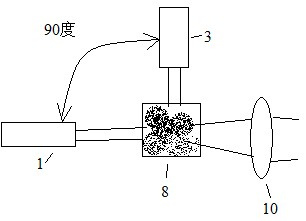
[0037] The difference from Embodiment 1 is that in this embodiment, the measurement of dynamic light scattering and static light scattering respectively adopts two laser light sources: the first laser light source 1 and the second laser light source 10, by figure 2 , ...

Embodiment 3

[0039] When static light scattering is used to measure larger particles, such as particles with hundreds of microns, the focal length of the lens 9 in Embodiment 1 needs to be relatively long, so that the size of the instrument formed is relatively long. In order to reduce the size of the instrument, in this embodiment, the arrangement position of the Dove prism 5 in Embodiment 1 has been changed, as Figure 4 shown. In the image method measurement, the image enlarged by the microscope objective lens 4 is directly sent to the area array digital camera or video camera 7 after passing through the half-transparent mirror 6 . The dynamic scattered light or static scattered light in the light scattering measurement is received by the lens 9 and passes through the dove prism 5 and then passes through the half mirror 6 to the area array digital camera or video camera 7 .

[0040] In this embodiment, as in Embodiment 2, the dynamic light scattering measurement and the static light sc...


PUM


Abstract

The invention discloses a multi-method combined particle size analyzer which is characterized in that a laser source, a non-monochromatic lighting source, a microobjective, a Dove prism or two 90-degree turning prisms or total reflection mirrors, a half transparent and half reflecting mirror, an array digital camera or a video camera, a sample cell and a lens form two light path structures, wherein one light path irradiates samples in the sample cell from the non-monochromatic lighting source, and an image magnified by the microobjective is transmitted to the array digital camera through the Dove prism and the half transparent and half reflecting mirror; and the other light path irradiates the samples in the sample cell from the laser lighting source, and the image magnified by the lens is transmitted to the array digital camera through the half transparent and half reflecting mirror. The multi-method combined particle size analyzer has the benefits of combining multiple measuring methods together by using one digital camera, expanding the upper limit and the lower limit of the particle size analyzer by using a simple structure, enabling the measurement range of the particle size analyzer to be from nanometer to hundreds of microns, meeting the requirement of wide-range size distribution measurement, and being capable of giving morphology parameters of particles by using the image method simultaneously.

Description

technical field [0001] The invention relates to a particle size measuring device which combines an image method and a light scattering method, in particular to a particle size meter whose measurement range can be from nanometer, submicron to micron. Background technique [0002] In recent years, with the development of CCD and CMOS digital cameras, image-based particle size analyzers that use digital cameras instead of eyepieces on traditional microscopes have been widely used. Limited by the theoretical image resolution of the optical microscope, the measurement lower limit of the image-based particle size analyzer is generally above 0.5 microns, and the upper limit can be determined according to the magnification of the microscope objective lens used. The dynamic light scattering particle size analyzer is mainly used for the particle size measurement of nanoparticles. Generally, the lower limit of measurement is about 1 nanometer, and the upper limit is 3-5 microns. Altho...

Claims


Application Information

Patent Timeline
Patent Type & Authority Applications(China)
IPC IPC(8): G01N15/02
Inventor 蔡小舒苏明旭
Owner UNIV OF SHANGHAI FOR SCI & TECH
Why Eureka
Try Eureka