Multi-method combined particle size analyzer
A particle size analyzer and multi-method technology, applied in the field of particle size analyzer, can solve the problems of undetectable and small Brownian motion, and achieve the effect of expanding the structure and meeting the requirements of wide-range particle size distribution measurement.
- Summary
- Abstract
- Description
- Claims
- Application Information
AI Technical Summary
Problems solved by technology
Method used
Image
Examples
Embodiment 1
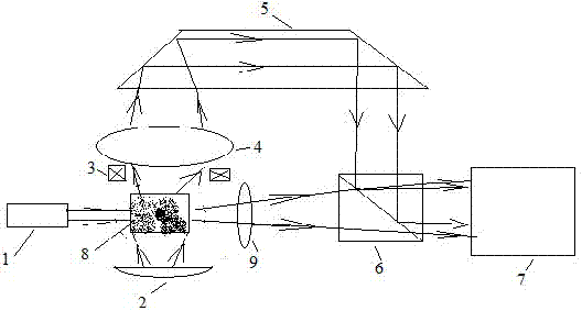
[0031] A multi-method fusion particle size analyzer, consisting of figure 1 As shown, the particle size analyzer consists of a laser light source 1, a first lighting source 2, a second lighting source 3, a microscope objective lens 4, a Dove prism 5, a half mirror 6, an area array digital camera or video camera 7, a sample The pool 8 and the lens 9 are combined into two light path structures, one path is that the light emitted from the illumination source 2 irradiates the sample in the sample pool 8, and the sample pool 8 is located on the observation surface of the microscopic objective lens 4, and the microscopic objective lens 4 will magnify the image After passing through the dove prism 5 and then passing through the semi-transparent mirror 6 to the area array digital camera or video camera 7; the other way is that the light emitted by the laser light source 1 is irradiated on the sample in the sample pool 8, and the lens 9 passes the enlarged image through the half-mirror...
Embodiment 2
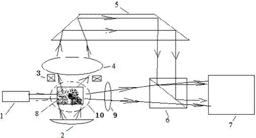
[0036] In Example 1, both static light scattering and dynamic light scattering measure forward scattered light. Because dynamic light scattering measures nanometer to submicron particles, the dynamic scattered light intensity of these tiny particles is relatively weak, but the scattered light intensity in all directions is relatively uniform, and ambient stray light will cause dynamic scattered light of these tiny particles. A lot of noise. However, the forward scattered light of micron-sized particles is strong, and the side scattered light is relatively weak, so the forward measurement is not easily disturbed by ambient stray light. In order to solve this problem, propose embodiment 2, by figure 2 shown.
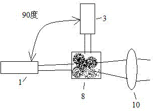
[0037] The difference from Embodiment 1 is that in this embodiment, the measurement of dynamic light scattering and static light scattering respectively adopts two laser light sources: the first laser light source 1 and the second laser light source 10, by figure 2 , ...
Embodiment 3
[0039] When static light scattering is used to measure larger particles, such as particles with hundreds of microns, the focal length of the lens 9 in Embodiment 1 needs to be relatively long, so that the size of the instrument formed is relatively long. In order to reduce the size of the instrument, in this embodiment, the arrangement position of the Dove prism 5 in Embodiment 1 has been changed, as Figure 4 shown. In the image method measurement, the image enlarged by the microscope objective lens 4 is directly sent to the area array digital camera or video camera 7 after passing through the half-transparent mirror 6 . The dynamic scattered light or static scattered light in the light scattering measurement is received by the lens 9 and passes through the dove prism 5 and then passes through the half mirror 6 to the area array digital camera or video camera 7 .
[0040] In this embodiment, as in Embodiment 2, the dynamic light scattering measurement and the static light sc...
PUM
 Abstract
Description
Claims
Application Information
 - R&D
- Intellectual Property
- Life Sciences
- Materials
- Tech Scout
- Unparalleled Data Quality
- Higher Quality Content
- 60% Fewer Hallucinations
Browse by: Latest US Patents, China's latest patents, Technical Efficacy Thesaurus, Application Domain, Technology Topic, Popular Technical Reports.
© 2025 PatSnap. All rights reserved.Legal|Privacy policy|Modern Slavery Act Transparency Statement|Sitemap|About US| Contact US: help@patsnap.com


