Supercharge Your Innovation With Domain-Expert AI Agents!

Heat pipe test method

A test method and heat pipe technology, applied in the direction of thermal development of materials, etc., can solve the problems of central processing unit operation error, permanent failure of central processing unit, failure and other problems

Inactive Publication Date: 2011-06-01
黄玉杰
View PDF0 Cites 0 Cited by
  • Summary
  • Abstract
  • Description
  • Claims
  • Application Information

AI Technical Summary

Problems solved by technology

When the central processing unit is running at high speed, if the temperature of the central processing unit exceeds its normal operating temperature range, the central processing unit is very likely to have an operation error or temporarily fail, which will cause the host computer to crash
In addition, when the temperature of the central processing unit far exceeds its normal operating temperature range, it is even very likely to damage the transistors inside the central processing unit, thus causing permanent failure of the central processing unit

Method used


Image

  • Heat pipe test method
  • Heat pipe test method
  • Heat pipe test method

Examples


Embodiment Construction

[0063] Below in conjunction with accompanying drawing, structural principle and working principle of the present invention are specifically described:

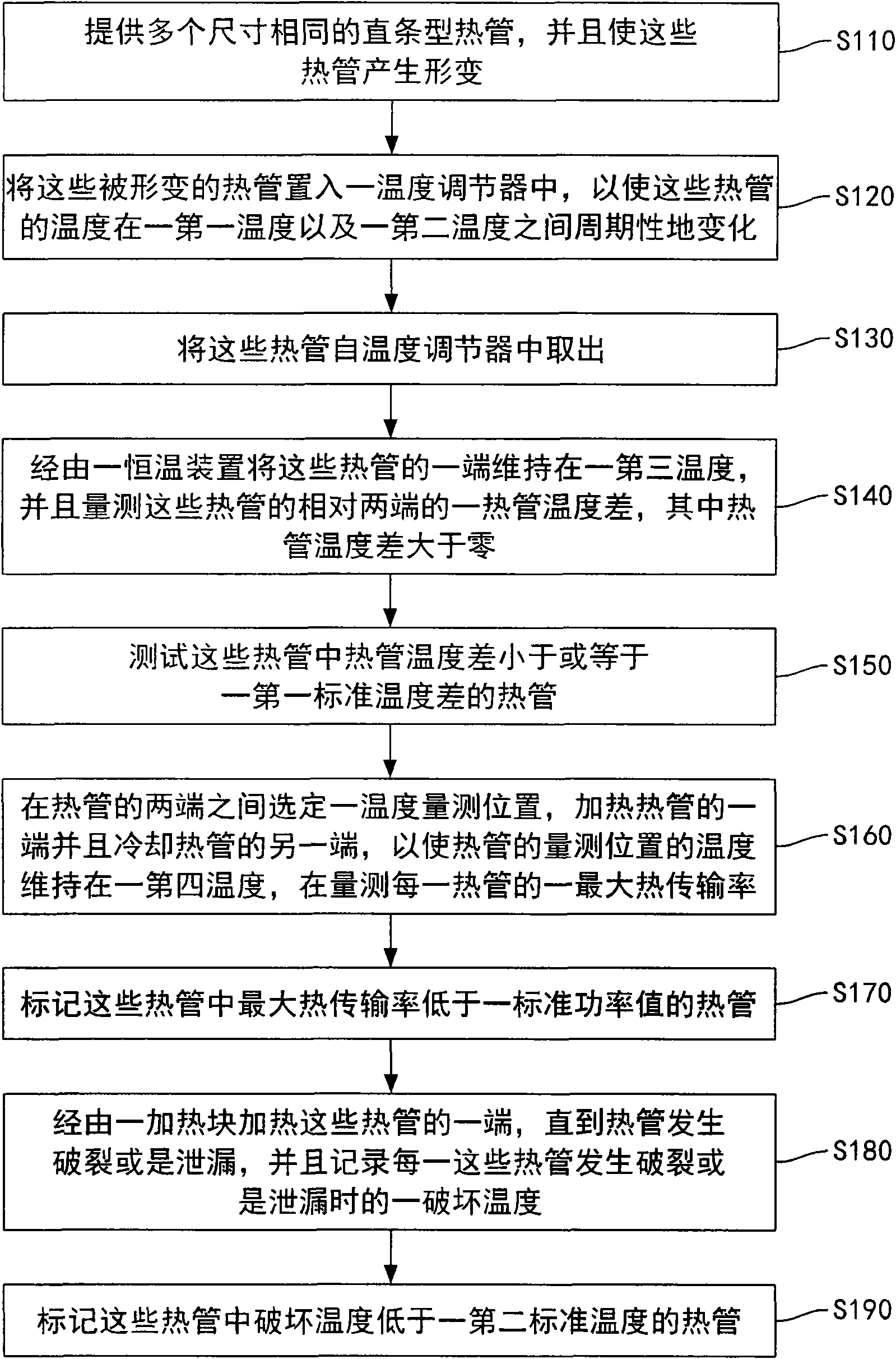
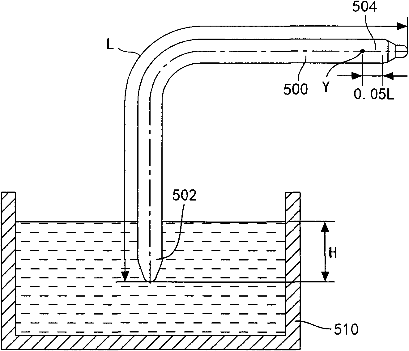
[0064] Please refer to figure 1 , which is a schematic diagram of a heat pipe testing method according to an embodiment of the present invention. First, as shown in step S110, a plurality of heat pipes having the same shape and the same size are provided. In this embodiment, the length of each heat pipe is L, and the shape of each heat pipe is a straight cylinder. After that, These heat pipes are deformed, and the position and size of the deformed part of each heat pipe are consistent. If the deformation is a bending deformation, the curvature of the bending is the same. If the deformation is extrusion deformation, the thickness of the extruded heat pipes is the same, that is, the shape and size of the heat pipes after deformation treatment are the same. In this embodiment, the end portion 502 of the heat pipe 500 is extrud...


PUM


Abstract

The invention discloses a heat pipe test method comprising the following steps of: providing a plurality of straight stripped heat pipes with same size and enabling the heat pipes to deform; placing the deformed heat pipes into a temperature regulator so that the temperatures of the heat pipes periodically change between a first temperature and a second temperature; taking the heat pipes out of the temperature regulator; keeping the temperatures of one ends of the heat pipes at a third temperature by using a thermostatic apparatus, and measuring a heat pipe temperature difference between two opposite ends of the heat pipes, and marking heat pipes with a heat pipe temperature difference being larger than a standard temperature difference in the heat pipes.

Description

technical field [0001] The invention relates to a test method of a heat dissipation component, in particular to a test method of a heat pipe. Background technique [0002] In recent years, with the rapid development of computer technology, the operating speed of the computer has been continuously increased, and the heat generation rate of the electronic elements inside the computer mainframe has also been continuously increased. In order to prevent the electronic components inside the computer host from overheating, resulting in temporary or permanent failure of the electronic components, a heat dissipation module is placed inside the computer host in the prior art to dissipate the heat generated by the electronic components outside the computer host . [0003] Among these electronic components, the central processing unit (CPU) is the main source of heat generation in the electronic components of the computer host. When the central processing unit is running at high speed...

Claims


Application Information

Patent Timeline
Patent Type & Authority Applications(China)
IPC IPC(8): G01N25/20
Inventor 王锋谷郑懿伦杨智凯
Owner 黄玉杰
Features
  • R&D
  • Intellectual Property
  • Life Sciences
  • Materials
  • Tech Scout
  • Unparalleled Data Quality
  • Higher Quality Content
  • 60% Fewer Hallucinations
Learn More