
LED (light-emitting diode) lighting circuit

A LED lighting and circuit technology, applied in lighting devices, lamp circuit layout, electric light source, etc., can solve problems such as LED damage, and achieve the effect of avoiding sudden changes in current

Inactive Publication Date: 2011-06-01
KONKA GROUP
View PDF0 Cites 10 Cited by
  • Summary
  • Abstract
  • Description
  • Claims
  • Application Information

AI Technical Summary

Problems solved by technology

[0004] The purpose of the present invention is to provide an LED lighting circuit, aiming to solve the problem that the existing LED lighting circuit will cause LED damage

Method used


Image

  • LED (light-emitting diode) lighting circuit
  • LED (light-emitting diode) lighting circuit
  • LED (light-emitting diode) lighting circuit

Examples


Embodiment Construction

[0016] In order to make the object, technical solution and advantages of the present invention clearer, the present invention will be further described in detail below in conjunction with the accompanying drawings and embodiments. It should be understood that the specific embodiments described here are only used to explain the present invention, not to limit the present invention.

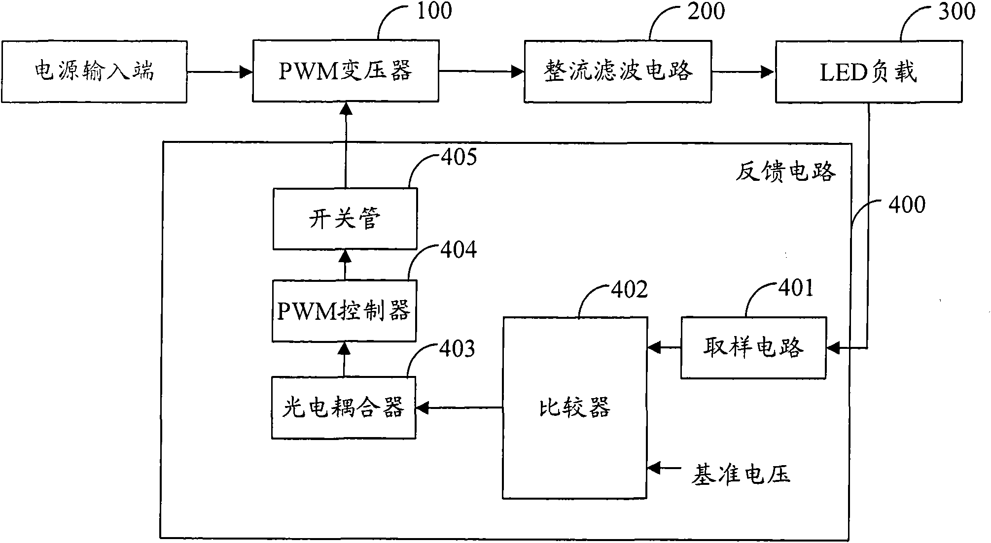
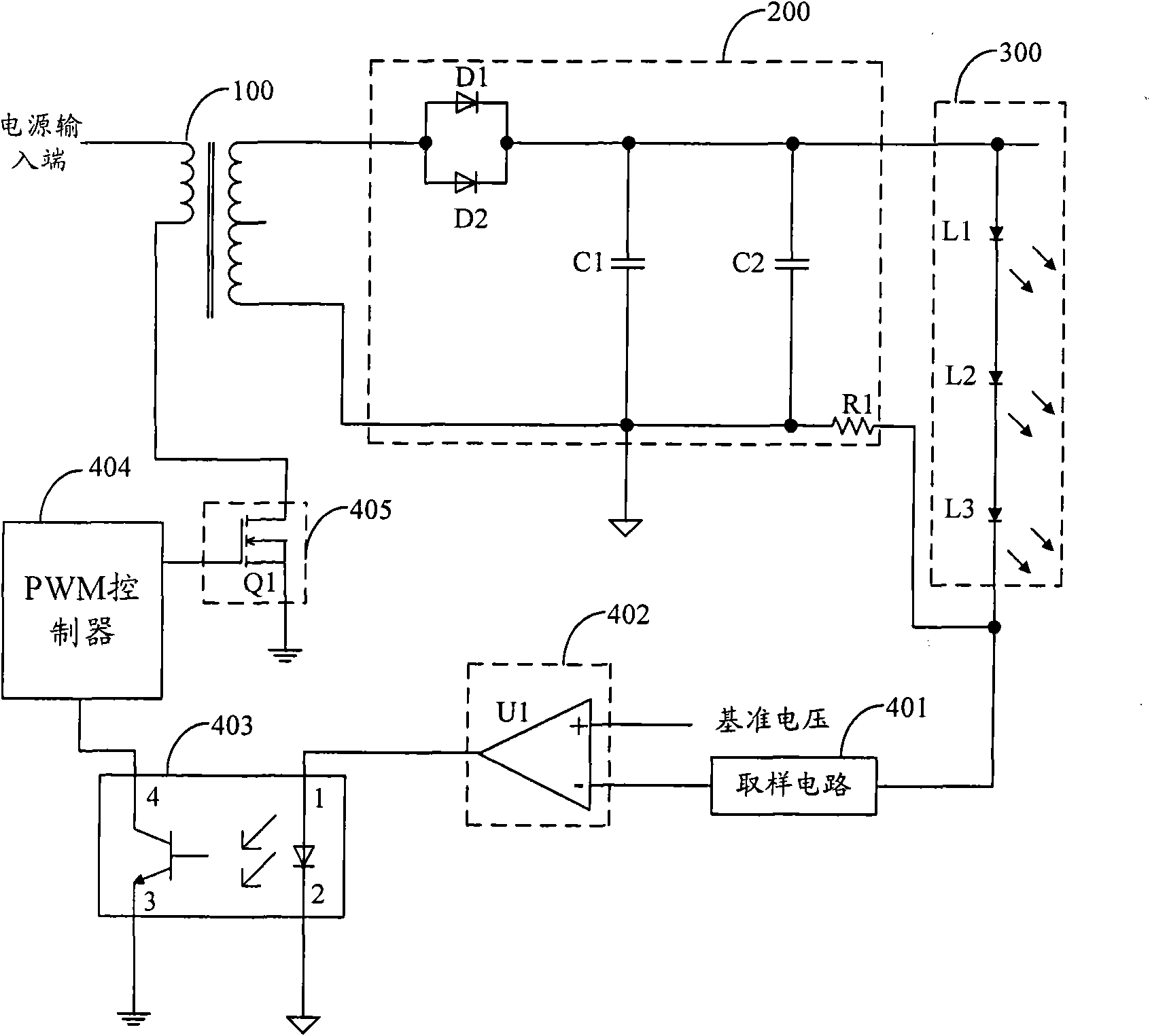
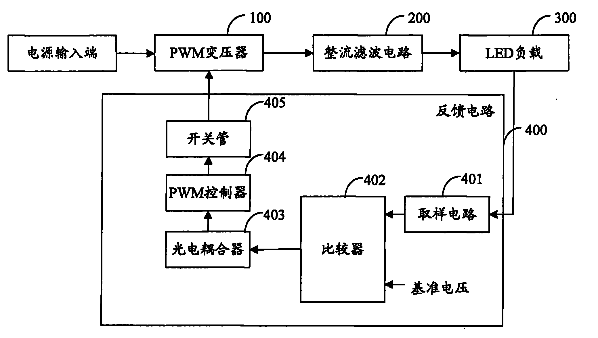
[0017] figure 1 The structure of the LED lighting circuit provided by the embodiment of the present invention is shown.

[0018] The LED lighting circuit includes a PWM transformer 100 , a rectification and filtering circuit 200 , an LED load 300 and a feedback circuit 400 .

[0019] The PWM transformer 100 is connected to the input end of the power supply, the rectification filter circuit 200 is connected to the output end of the PWM transformer 100, the LED load 300 is connected to the output end of the rectification filter circuit 200, the input end of the feedback circuit 400 is connected to t...


PUM


Abstract

The invention is suitable for the technical field of an LED (light-emitting diode), and provides an LED lighting circuit. The LED lighting circuit is composed of a PWM (pulse-width modulation) transformer, a rectifier filter circuit, an LED load and a feedback circuit. In the invention, by adopting the feedback circuit in the LED lighting circuit, the current change of the LED load is effectively controlled, the current of the LED load is kept constant, and the damage to an LED due to abrupt current change is avoided.

Description

technical field [0001] The invention belongs to the technical field of LEDs, in particular to an LED lighting circuit. Background technique [0002] LED lighting has been widely used in people's daily life, and the use of LED lighting has the advantages of low energy consumption, long service life and environmental protection. [0003] The existing LED lighting circuit adopts a constant voltage circuit. This kind of lighting circuit will cause damage to the LED load during use, because the LED is a device with a negative temperature coefficient. When the temperature rises, its impedance will decrease, which will cause current flow. The current through the LED increases, causing the temperature of the LED to rise rapidly. If the current is not controlled, the LED will be damaged. Contents of the invention [0004] The purpose of the present invention is to provide an LED lighting circuit, aiming to solve the problem that the existing LED lighting circuit will cause damage ...

Claims


Application Information

Patent Timeline
Patent Type & Authority Applications(China)
IPC IPC(8): H05B37/02H02M7/08H02M1/14
Inventor 乔景明
Owner KONKA GROUP
Learn More