Sealing system between a shroud segment and a rotor blade tip and manufacturing method for such a segment

A blade tip, segment technology, used in the production of shell segments, can solve problems such as failure

Inactive Publication Date: 2011-06-01
SIEMENS AG
View PDF1 Cites 6 Cited by
  • Summary
  • Abstract
  • Description
  • Claims
  • Application Information

AI Technical Summary

Problems solved by technology

This wear condition can lead to catastrophic failure

Method used


Image

  • Sealing system between a shroud segment and a rotor blade tip and manufacturing method for such a segment
  • Sealing system between a shroud segment and a rotor blade tip and manufacturing method for such a segment
  • Sealing system between a shroud segment and a rotor blade tip and manufacturing method for such a segment

Examples


Embodiment Construction

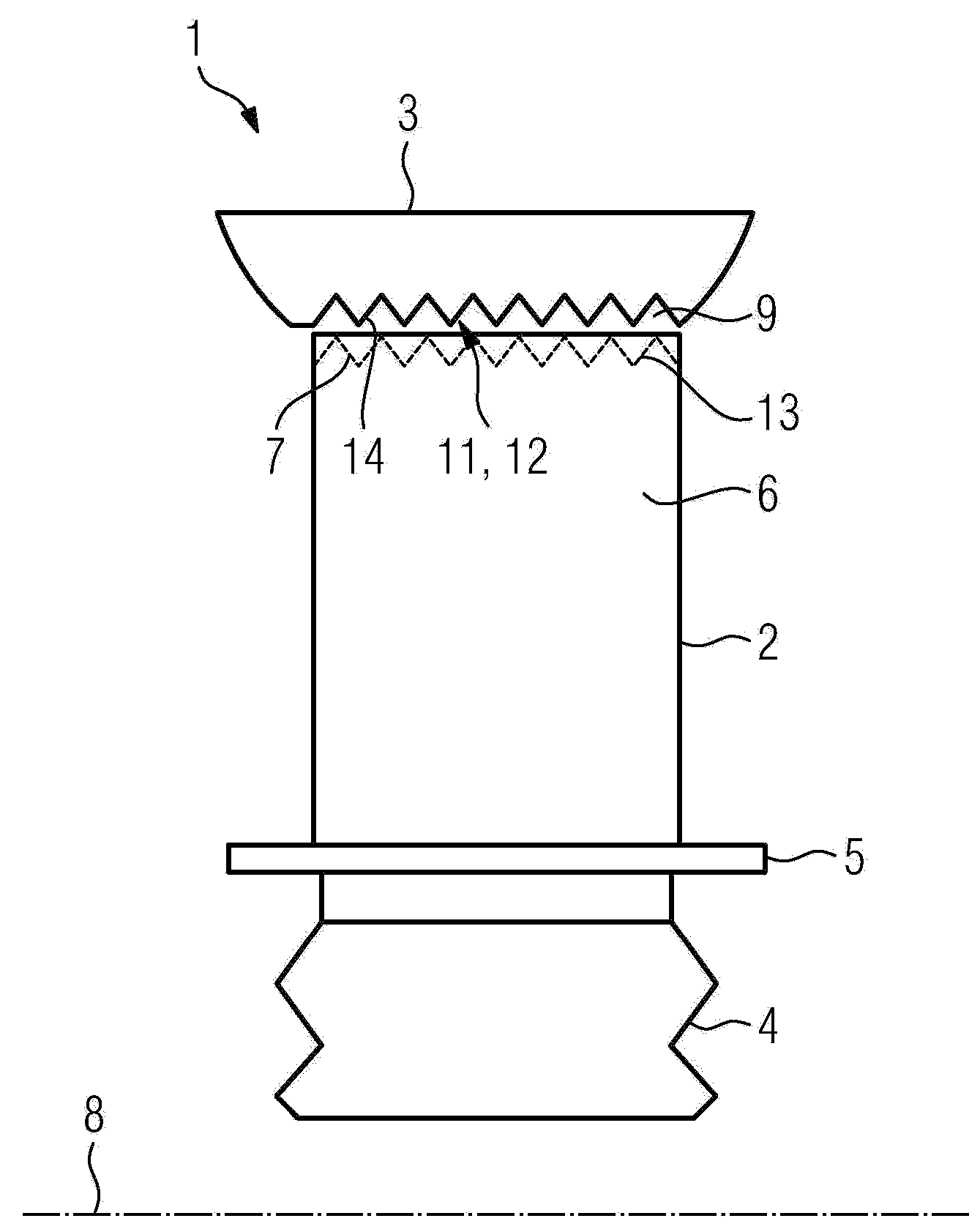
[0027] figure 1 An arrangement 1 according to the invention is shown, comprising a gas turbine blade 2 and a casing section 3 .

[0028] The gas turbine blade 2 is composed of a blade root 4 , a platform 5 and an airfoil 6 terminating radially at a blade tip 7 . The blades 2 are mounted in a not shown manner in a not shown rotor extending along a machine axis 8 (respectively the rotor's axis of rotation). The housing section 3 surrounds the rotor circumferentially.

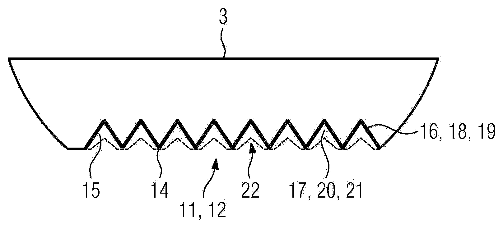
[0029] A gap 9 is provided between the blade tip 7 and the surface 11 of the shell section 3 facing the blade tip 7 to maintain the necessary clearance between the rotating part and the fixed part. The surface 11 has a first surface structure 12 which improves the aerodynamic efficiency by inhibiting the secondary flow over the blade tip 7, the bypassing of which reduces the power output. The serration 12 is formed by circumferential grooves 22 having a triangular cross-sectional shape separating triangular cir...


PUM

PropertyMeasurementUnit
thicknessaaaaaaaaaa
thicknessaaaaaaaaaa

Abstract

The invention relates to an arrangement (1) comprising a turbine blade, which comprises at least a root (4), an airfoil and a tip (7) and which is mounted to a rotor by means of its root (4), which rotor is extending along a machine axis (8) and a circumferential casing segment (3), which is comprising a surface (11), which is facing tips (7) of the blades (2), wherein the surface (11) is structured. Further it relates to a method to produce such a casing segment (11). It is an object of the invention to increase efficiency without limiting the operational range of the turbine. The object is achieved by providing the surface (11) at least partially with an at least partially ceramic coating (15). Further it is suggested to produce the casing segment by the steps of: machining a first structure (12) into the surface (11), providing the surface (11) with a ceramic coating (15).

Description

technical field [0001] The invention relates to an arrangement comprising a turbine blade and a circumferential casing section, wherein said turbine blade comprises at least a root, an airfoil and a tip and is mounted by means of its root to a rotor extending along a machine axis, said circumferential The shell section comprises a surface facing the tip of the blade, wherein the surface is structured. Furthermore, the invention relates to a method of producing a casing section comprising a surface facing the blade tip of a turbine blade mounted to a rotor extending rotatably along a machine axis. Background technique [0002] The most important research goal in the field of modern gas turbines is to improve efficiency. Other important aspects are operational flexibility, low maintenance costs, high availability and low emissions. The latter objective is directly related to increased efficiency, where a secondary feature is operational stability. [0003] Basic thermodynam...

Claims


Application Information

Patent Timeline
Patent Type & Authority Applications(China)
IPC IPC(8): F01D5/20F01D11/12
CPCF01D5/20F01D11/122F05D2250/11F05B2250/23F05B2250/11F05D2240/11F05D2250/23F05B2240/11Y10T29/49229
Inventor X-H·李S·舒金
Owner SIEMENS AG
Why Eureka
Try Eureka