Train control system and railway control system

A technology of train control system and control system, which is applied in the field of control force system, and can solve problems such as inability to determine control instructions, time-consuming, and impact

Inactive Publication Date: 2011-06-08
HITACHI LTD
View PDF5 Cites 11 Cited by
  • Summary
  • Abstract
  • Description
  • Claims
  • Application Information

AI Technical Summary

Problems solved by technology

[0004] However, in these methods, the trains communicate with each other, and the control command cannot be determined until the information of all the trains is collected, so it takes time until the control is determined
In addition, although it is described that the control force is sequentially reduced starting from the train with the smallest delay information, since the delay information is determined based on the match with the reference driving pattern, it is difficult to apply it when the delay occurs when there is a significant deviation from the reference driving pattern. driving situation
In addition, based on the above reasons, it is also conceivable to select a train that is different from the control object that is originally involved and implement control. In this case, it will further cause unnecessary delays, and it will also affect the subsequent trains.
In addition, because the distance between trains is not considered, and the influence of the signal pattern of the subsequent train by each train is not considered, it is possible to further cause unnecessary deceleration of the subsequent train.

Method used


Image

  • Train control system and railway control system
  • Train control system and railway control system
  • Train control system and railway control system

Examples


Embodiment 1

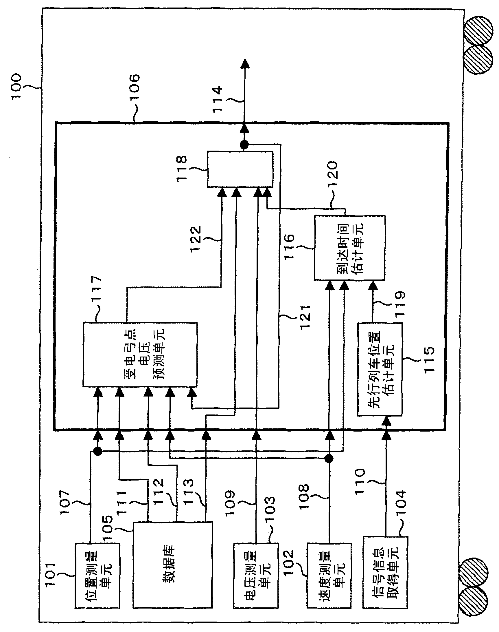
[0071] figure 1 This is an example of a train equipped with a train control system for realizing the present invention. The train control system used to realize the present invention consists of a position measuring unit 101 for measuring the position of the train, a speed measuring unit 102 for measuring the speed of the train, and a voltage on the pantograph of the train (hereinafter referred to as Pantograph point voltage) voltage measurement unit 103, signal information acquisition unit 104 for acquiring signal information given to the own train, database 105 for storing performance of the train, position of the substation, and time interval with the preceding train for control 1. The driving control unit 106 is formed. In addition, the driving control unit 106 uses the train position 107 obtained from the position measurement unit 101, the train speed 108 obtained from the speed measurement unit 102, and the pantograph of the own train obtained from the voltage measureme...

Embodiment 2

[0136] Next, use Figure 12 to Figure 14 A second embodiment in which control is performed based on peak cancellation command information from a substation will be described.

[0137] Figure 12 It is an example of a substation in the case of the second embodiment. The substation is composed of the following components: a substation current supply unit 1201, which supplies current to overhead wires; a substation current monitoring unit 1203, which monitors the current of the substation current supply unit 1201, and judges whether the supply load exceeds a specified value, and if it exceeds When the predetermined value is reached, the peak value elimination command information 1202 from the substation to the train is output; the substation information sending unit 1204 sends the peak value elimination command information 1202 from the substation to the train to all trains in the corresponding area.

[0138] Figure 13 It is an example of the train in the case of the second e...

Embodiment 3

[0141] Next, use Figure 15 ~ Figure 17 A third embodiment in which control is performed based on information from an operation management system that grasps the state of each train will be described.

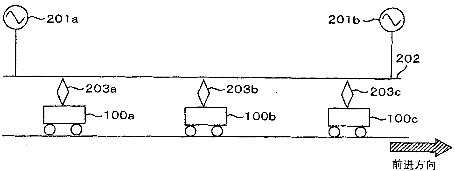
[0142] Figure 15 It is a railway system in which each train is controlled based on information from an operation management system that grasps the state of each train. In addition, it is assumed that the trains 100a and 100b are running, and 100b is the preceding train. In this case, it is shown that the operation management system 1501 having grasped the train state calculates the time ratio Ht / Qt 1503 of the preceding train 100b and the subsequent train 100a based on the train state information 1502 of the preceding train 100b and timetable information not shown, and conveys to the subsequent train 100a, whereby the control is performed by the subsequent train 100a. In addition, although not shown in the figure, when another train (for example, 100c) exists after the subs...


PUM


Abstract

The invention provides a train control system. A driving control unit comprises a preceding train estimation unit which dynamically estimates the location of a preceding train according to signals obtained from a signal and information obtaining unit; an arrival time estimation unit which estimates the time when the present train arrives at the position of the preceding train according to the estimated position of the preceding train obtained from the preceding train estimation unit and the speed of the present train detected by a speed measuring unit; and a forecasting unit for pantograph point voltage, which forecasts the pantograph point voltage based on the location of the present train. Driving control commands are determined based on the time when the present train arriving at the position of the preceding train obtained from the arrival time estimation unit, the forecasting value of pantograph point voltage obtained from the forecasting unit for pantograph point voltage, and the actual pantograph point voltage obtained from a voltage measuring unit. In this way, the peak of a transformer station can be eliminated by actuating the driving control of the present train when influence on the signal mode of the following train is taken into consideration.

Description

technical field [0001] The present invention relates to a system for adjusting the control force of a train in order to eliminate a peak in a substation. Background technique [0002] On the suburban route of the metropolitan area, usually one substation supplies power to trains of 4 to 5 trains. Under such driving conditions, the power consumption of the train is usually adjusted by adjusting the acceleration and deceleration of the departure from the station, and the peak value of the power supplied by the substation is eliminated. However, such an adjustment is very difficult in the case of train delays, which can cause significant peaks in the substation due to simultaneous acceleration of multiple trains, etc. On the other hand, when the railway company and the electric power company predetermine the contracted power, and when the contracted power exceeds the contracted power, an excess charge has to be paid, it becomes more important to suppress the peak value of the ...

Claims


Application Information

Patent Timeline
Patent Type & Authority Applications(China)
IPC IPC(8): B60M3/02B61L27/00H02B5/00
Inventor 宫内努出纳和也铃木基也佐藤裕
Owner HITACHI LTD
Why Eureka
Try Eureka