Road roller

A technology of road rollers and rollers, applied in the field of road rollers, can solve the problems of increased construction costs, complicated transfer process, inconvenient transfer, etc., and achieve the effect of saving time and cost

Active Publication Date: 2011-06-08
XCMG CONSTR MACHINERY
View PDF6 Cites 16 Cited by
  • Summary
  • Abstract
  • Description
  • Claims
  • Application Information

AI Technical Summary

Problems solved by technology

[0007] Since the vibration wheel 200 is a steel roller, in order to prevent the steel wheel from damaging the road surface during driving, the relevant regulations do not allow the steel wheel to drive directly on the road. Therefore, the single-steel-wheel vibratory roller needs to be towed by vehicl

Method used


Image

  • Road roller
  • Road roller
  • Road roller

Examples


Embodiment Construction

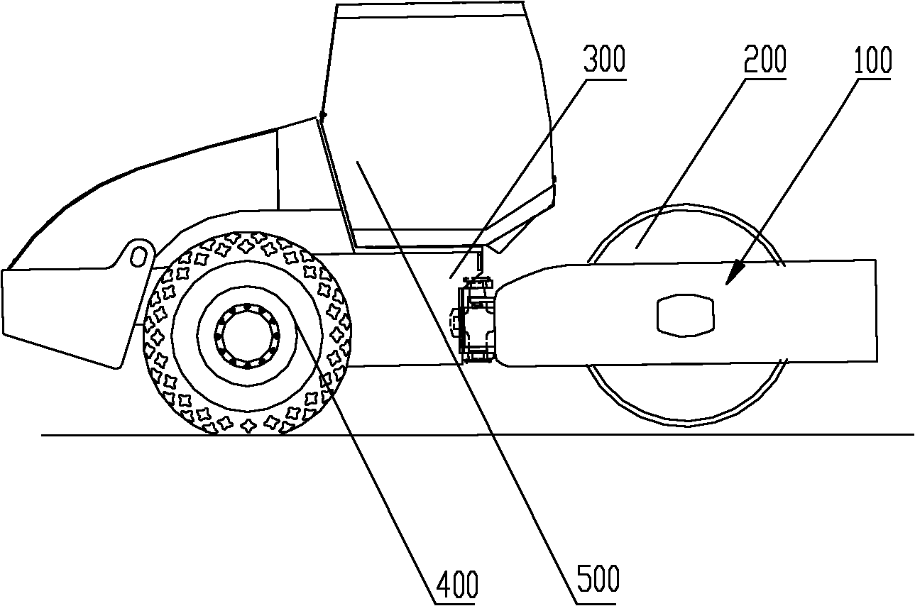
[0028] The core of the present invention is to provide a road roller, which can use wheels installed on the roller frame to travel when transferring the work site, so as to easily realize the self-transportation of the entire road roller.

[0029] In order to enable those skilled in the art to better understand the technical solutions of the present invention, the present invention will be further described in detail below with reference to the accompanying drawings and specific embodiments.

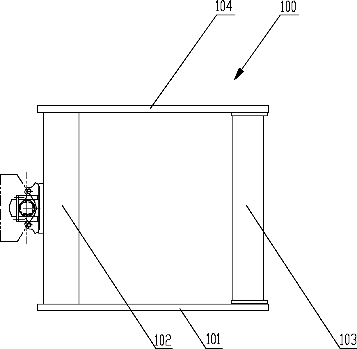
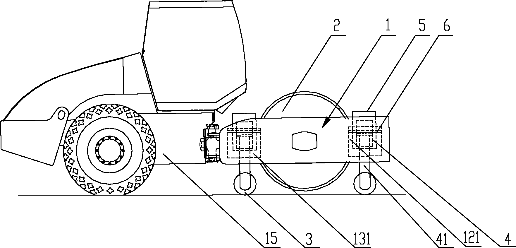
[0030] Please refer to image 3 , image 3 It is a schematic structural diagram of the first specific implementation of the road roller provided by the present invention; Figure 4 for image 3 Schematic diagram of the structure of the medium pressure wheel frame.

[0031] The single steel wheel vibratory roller in this embodiment includes a roller frame 1, which includes two side plates, namely a first side plate 11 and a second side plate 14, and also includes a front beam 13 and a rear beam 1...


PUM


Abstract

The invention discloses a road roller, which comprises a pinch roller frame and a vibrating wheel which is arranged in the pinch roller frame. The road roller is characterized by also comprising wheels and elevating devices for controlling the wheels to ascend and descend relative to the vibrating wheel, wherein the wheels are connected with the pinch roller frame through the elevating devices. When the road roller is in the working state, the wheels can be elevated and retracted by the elevating devices, and the vibrating wheel runs; and when the road roller is required to be transported to another place, the wheels are lowered by the elevating devices, the vibrating wheel is lifted away from the road surface, the road roller walks under the action of the wheels and a back wheel, self-propelled traveling function is realized, and a special transportation tool is not needed for transferring the road roller, so that time and cost are saved for users.

Description

Technical field [0001] The invention relates to the technical field of engineering machinery, in particular to a road roller. Background technique [0002] Road rollers are indispensable machinery and equipment when building roads, and single-drum vibratory rollers are a type of road roller used to compact roadbed materials. [0003] Please refer to figure 1 with figure 2 , figure 1 It is a schematic structural diagram of a typical single-drum vibratory roller; figure 2 for figure 1 Schematic diagram of the structure of the middle pressure wheel frame [0004] The complete vehicle of a single steel wheel vibratory roller usually consists of a cab 500, a rear frame 300, a tire 400, a vibrating wheel 200, and a roller frame 100. The rear frame 300 is located at the rear of the vehicle, and tires 400 are arranged on both sides. The rear frame 300 and the pressure wheel frame 100 located at the front of the vehicle are hinged by a hinged shaft. The pressure wheel frame 100 is composed...

Claims


Application Information

Patent Timeline
IPC IPC(8): E01C19/28
Inventor 周保刚林栋冰陆昕
Owner XCMG CONSTR MACHINERY
Why Eureka
Try Eureka