Self-driven remote control

A remote control, self-driven technology, applied in the direction of instruments, generators/motors, piezoelectric effect/electrostrictive or magnetostrictive motors, etc., can solve the problems of environmental risks and replacement costs, and achieve compact structure and exquisite design. , make simple effects

Inactive Publication Date: 2015-01-14
HUAZHONG UNIV OF SCI & TECH
View PDF8 Cites 0 Cited by
  • Summary
  • Abstract
  • Description
  • Claims
  • Application Information

AI Technical Summary

Problems solved by technology

As we all know, the use of batteries will cause many problems. Although many batteries can be reused now, they will still cause certain environmental risks and replacement costs.

Method used


Image

  • Self-driven remote control
  • Self-driven remote control
  • Self-driven remote control

Examples


Embodiment 1

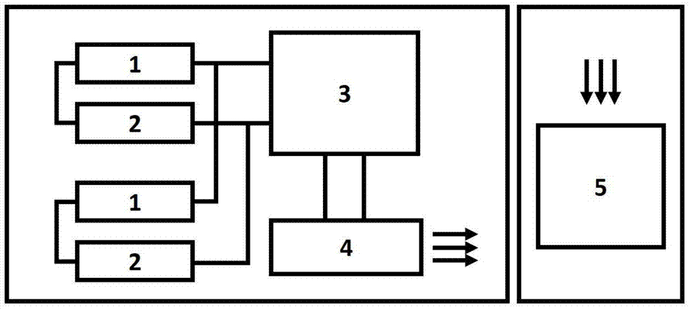
[0031] figure 1 It is a schematic diagram of the overall structure of a self-driven remote controller according to the present invention, as figure 1 As shown, there is a group of flexible generators 2 under each push switch 1 of a self-driven remote control. When the push switch 1 is pressed, the circuit connecting the two ends of the switch 1 is turned on to form a closed loop. At the same time, the push switch drives The flexible generator deforms to generate current, and the AC current signal is processed by the signal processing system 3 and becomes a wireless driving signal, thereby driving the wireless signal transmitting device 4 to transmit the control signal, and finally received by the signal receiving unit 5 .

[0032] Wherein, in order to realize the channel gating function of the remote controller, in the signal processing system 3, signal processing functions such as these can be realized:

[0033] When a key is pressed, the signal processing system 3 recognize...

Embodiment 2

[0044] Other components in embodiment 2 are similar to those in embodiment 1, and embodiment 2 mainly describes the function of performing multiple gates.

[0045] For different push switches and signal processing system 3 and flexible generating set 2 in the circuit series delay device, such as delay circuit, etc., this delay circuit can be set at the input interface of signal processing system 3, so for complex The time delay generated by the delay circuit is used for coding when the channel is selected, and multiple switches can be pressed at the same time to realize the channel selection.

Embodiment 3

[0047] Other components in embodiment 3 are similar to those in embodiment 1, and embodiment 3 mainly describes the function of performing multiple gates.

[0048] like Figure 7 As shown, the number of flexible generating units connected in parallel to the flexible generating set under each push switch 1 of the keyboard of the self-driving remote controller is not the same. In this case, the following signal processing system 3 will The current or voltage signal generated after the switch 1 is pressed is encoded for the corresponding channel gating, thereby realizing the gating of multiple channels.

[0049] To sum up, through the self-driven remote control of the present invention, the energy generated by pressing the remote control by the human body can be collected to drive the remote control, realizing the self-driving function of the remote control, saving energy and environmental protection, and greatly increasing the size of the remote control. durability; at the same...


PUM


Abstract

The invention discloses a self-driven remote control. The remote control comprises a pressing keyboard, signal source units, a signal processing system, a wireless signal transmitting device and a shell, wherein a signal source unit is arranged below each push switch in the pressing keyboard; one end of each push switch is connected with a corresponding signal source unit, and the other end of each push switch is connected with the signal processing system; and the other end of the corresponding signal source unit is connected with the signal processing system. According to the self-driven remote control disclosed by the invention, because flexible power generation units serve as the signal source units, the beneficial effects of saving energy, protecting the environment and greatly improving the durability of the remote control are achieved.

Description

technical field [0001] The invention belongs to the field of converting mechanical energy into electric energy and wireless signal transmission, and more specifically relates to a self-driven remote controller. Background technique [0002] With the development of electronic science and technology, the power consumption of electronic products is gradually decreasing. Although there are many low-power electronic products, most of these electronic products cannot be separated from the use of external power sources. The so-called external power sources mainly refer to batteries. As we all know, the use of batteries will cause many problems. Although many batteries are now reusable, they still cause certain environmental risks and replacement costs. [0003] As far as the remote control is concerned, the energy consumption required for a single transmission of a wireless control signal is relatively low. If the mechanical energy generated when the human body presses the remote ...

Claims


Application Information

Patent Timeline
Patent Type & Authority Applications(China)
IPC IPC(8): G08C23/04H02N2/18
Inventor 周军钟俊文钟其泽
Owner HUAZHONG UNIV OF SCI & TECH
Why Eureka
Try Eureka