Biopsy device

A biopsy, optical fiber technology, used in medical science, sensors, endoscopes, etc., can solve problems such as manufacturing and assembly sealing difficulties

Active Publication Date: 2011-06-08
KONINK PHILIPS ELECTRONICS NV
View PDF4 Cites 11 Cited by
  • Summary
  • Abstract
  • Description
  • Claims
  • Application Information

AI Technical Summary

Problems solved by technology

Manufacturing and assembling this type of seal is difficult due to the small size and the variety of fibers that need to be introduced

Method used


Image

  • Biopsy device
  • Biopsy device
  • Biopsy device

Examples


Embodiment Construction

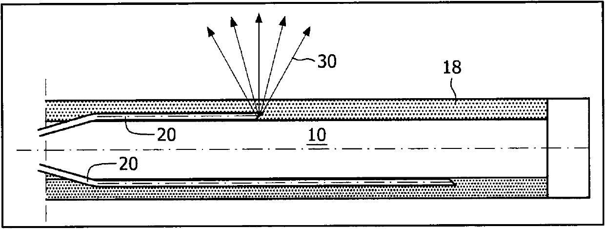
[0025] Such as figure 2 As shown, the shaft of the biopsy device according to the present invention comprises a configuration in which both the emitting and receiving fibers are embedded in a transparent material forming the shaft, which itself forms the outer surface of the biopsy device.

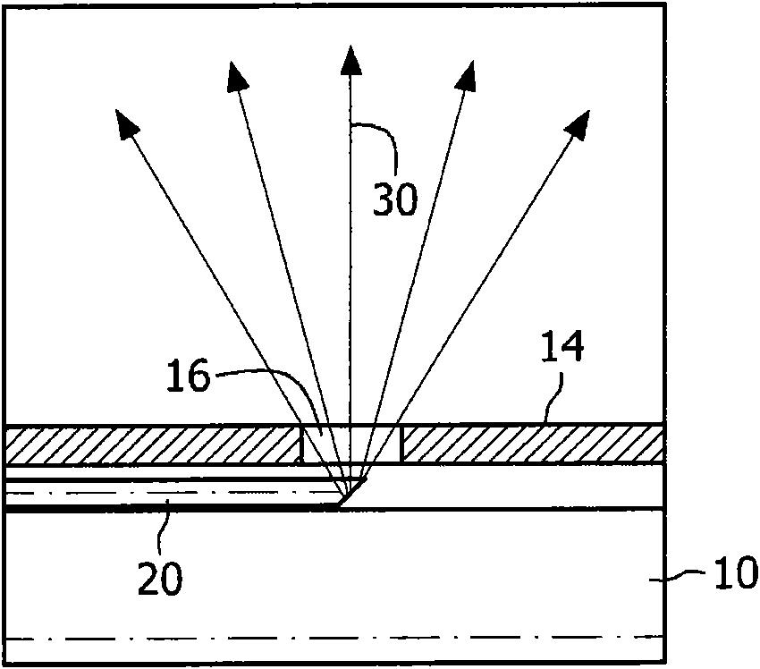
[0026] Accordingly, the shaft of the biopsy device comprises an inner space 10, a wall formed of a transparent material 18 and at least one optical fiber 20 for emitting and / or receiving light. In the figure, the light emitted through the fiber is indicated by arrow 30 .

[0027] The inner space 10 may also be a conventional probe, such as a hollow metal probe for biopsy procedures, with a transparent material 18 around the hollow metal probe.

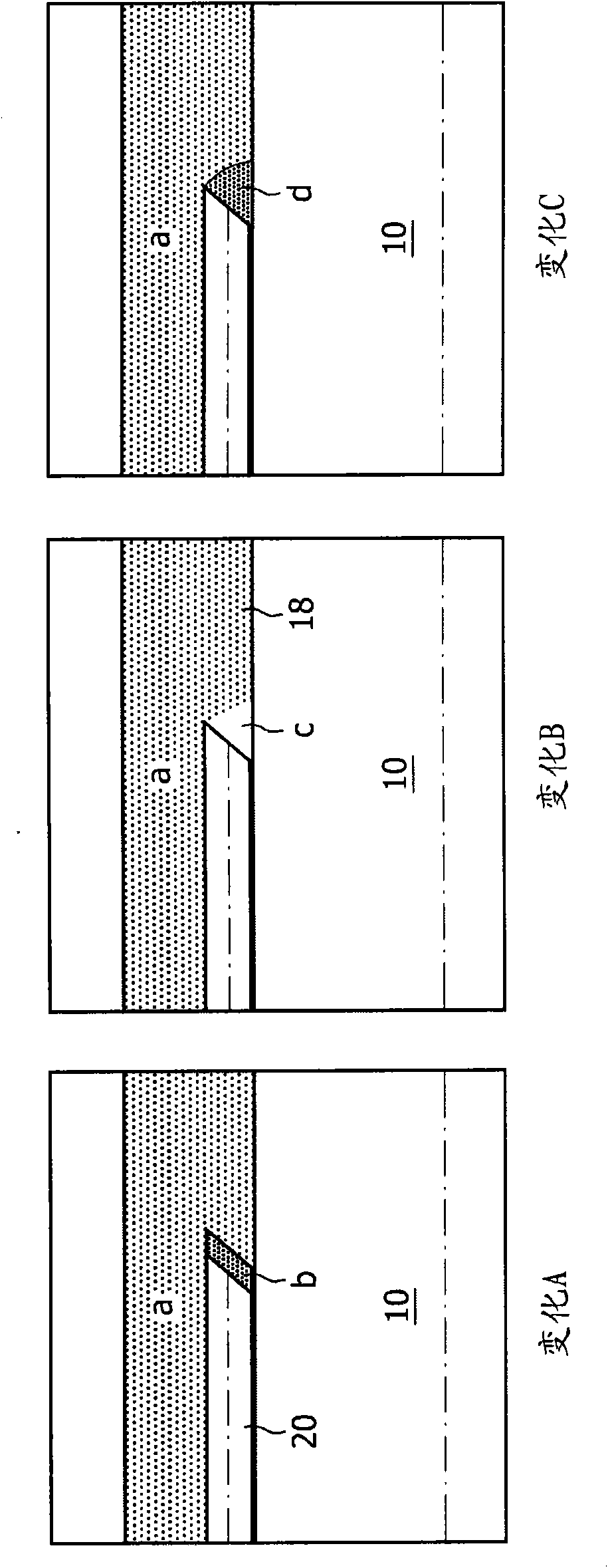
[0028] In order for the passage of light from the optical fiber 20 through the transparent material 18 into the tissue and vice versa to be unobstructed, the ends of the optical fiber 20 must be embedded in the transparent material.

[0029] In o...


PUM


Abstract

Biopsy needles equipped with fibres (20) allow tissue inspection to diagnoses. In order to allow detailed inspection side looking fibres should also be integrated around the needle. These fibres might be embedded in a transparent medium (18) to avoid direct contact of the sharp edges of the fibre to the tissue. A biopsy needle having such embedded fibres as well as a method for manufacturing said biopsy needle, based on curable transparent liquid, is provided by the invention.

Description

technical field [0001] The present invention generally relates to a biopsy device. In particular, the invention relates to biopsy devices comprising a shaft with optical fibers for optical examination. Background technique [0002] As shown in Figure 1, the optical fiber may be integrated within the shaft wall of the biopsy device. Optical inspection of the tissue surrounding the device is made possible by means of these fibers. Light from the launch fiber is coupled out through small holes in the outer surface of the device in a direction perpendicular to the axis of rotation of the device. This light will be scattered in the tissue. The same optical fiber or another optical fiber, also integrated in the device and located near the launch fiber, is used to collect the scattered light. Both the launch fiber and the collection fiber are arranged parallel to the axis of rotation of the device. Since the main direction of emitted or collected light travels along the direct...

Claims


Application Information

Patent Timeline
Patent Type & Authority Applications(China)
IPC IPC(8): A61B1/04A61B5/00A61B10/02
CPCA61B10/0233A61B5/0084A61B2019/5206A61B2017/00057A61B2090/306
Inventor A·L·布劳恩B·H·W·亨德里克斯C·A·N·M·范德夫吕滕
Owner KONINK PHILIPS ELECTRONICS NV
Why Eureka
Try Eureka