Biopsy guide with an ultrasound transducer and method of using same

a biopsy guide and transducer technology, applied in the field of biopsy guide system, can solve the problems of not having a perfectly sharp ultrasound beam, further complicating matters, and no guidance imaging may be available, so as to avoid mistakes during the procedure and improve awareness of nearby structures

Active Publication Date: 2015-12-01
KONINK PHILIPS ELECTRONICS NV
View PDF28 Cites 3 Cited by
  • Summary
  • Abstract
  • Description
  • Claims
  • Application Information

AI Technical Summary

Benefits of technology

[0013]It is an object of the invention to provide a biopsy guide system which allows for an improved flexibility in selecting an entry location for a biopsy needle while enabling monitoring an insertion of the biopsy needle. It is another object of the invention to provide a method of controlling the guidance of a biopsy needle using such biopsy guide system.
[0030]According to a further embodiment of the present invention, the multi-position biopsy guide system is adapted to acquire an ultrasound image in an image plane aligned with the biopsy path corresponding to the determined location of a biopsy needle guide. In other words, the proposed multi-position biopsy guide system may have a control device which is, on the one hand, able to determine the location of the biopsy needle guide and which, on the other hand, is able to control the 2D matrix ultrasound transducer such that an ultrasound image is acquired in an imaging plane which is aligned with the biopsy path of a biopsy needle guided by the biopsy needle guide in the determined location. Accordingly, ultrasound imaging may be automatically aligned with the biopsy path thereby allowing easy and fast monitoring of the process of introducing the biopsy needle.
[0033]According to a further embodiment of the present invention, the multi-position biopsy guide system is adapted to acquire ultrasound images in respective image planes aligned with the biopsy paths of each of the biopsy needle guides. In other words, as the 2D matrix ultrasound transducer may be able to acquire ultrasound images in any arbitrary image plane, it may be advantageous to acquire ultrasound image in imaging planes coinciding with each of the possible biopsy paths such that introduction of one or preferably several biopsy needles along the several possible biopsy paths may be observed quasi-simultaneously or alternately.
[0034]According to a further embodiment of the present invention, the biopsy needle guide is adapted for guiding the biopsy needle along a biopsy path at controllably variable angles. In other words, a biopsy needle guide may include provisions to allow for different tilting of a guided biopsy needle such that the biopsy needle may be introduced into a patient's tissue under a selectable angle. Accordingly, the introduction angle of the biopsy needle can be chosen such that a specific location of a region of interest may be reached with the biopsy needle. This may be particularly advantageous in case a biopsy needle guide may be mounted at the proposed multi-position biopsy guide system at different selected locations such as at azimuth locations or at elevation locations. Depending on the selected location, a different introduction angle may be required for the biopsy needle in order to reach a region of interest.
[0036]According to a further embodiment of the present invention, the 2D matrix ultrasound transducer is adapted to acquire 3D ultrasound images. The ability of a 2D matrix ultrasound transducer to acquire ultrasound images from a volume may allow for the ability of deriving 3D ultrasound images. Thereby, it is possible to provide a 3D or volume representation of a region of interest. Such 3D representation may even be time-dependent (sometimes referred to as “live 3D” or “4D”) by concatenating a plurality of 3D representations acquired in a time sequence. Biopsy needles may be guided within an acquired 3D image. Biopsy guidance in live 3D may provide better awareness of nearby structures and may thereby help to avoid mistakes during the procedure.

Problems solved by technology

To further complicate matters, the ultrasound beam does not have perfectly sharp boundaries.
A different needle guide location could be used, but since the biopsy needles path would not fall within the single available imaging plane, no guidance imaging may be available as the needle will not be visible until it passes through the imaging plane.

Method used


Image

  • Biopsy guide with an ultrasound transducer and method of using same
  • Biopsy guide with an ultrasound transducer and method of using same
  • Biopsy guide with an ultrasound transducer and method of using same

Examples


Embodiment Construction

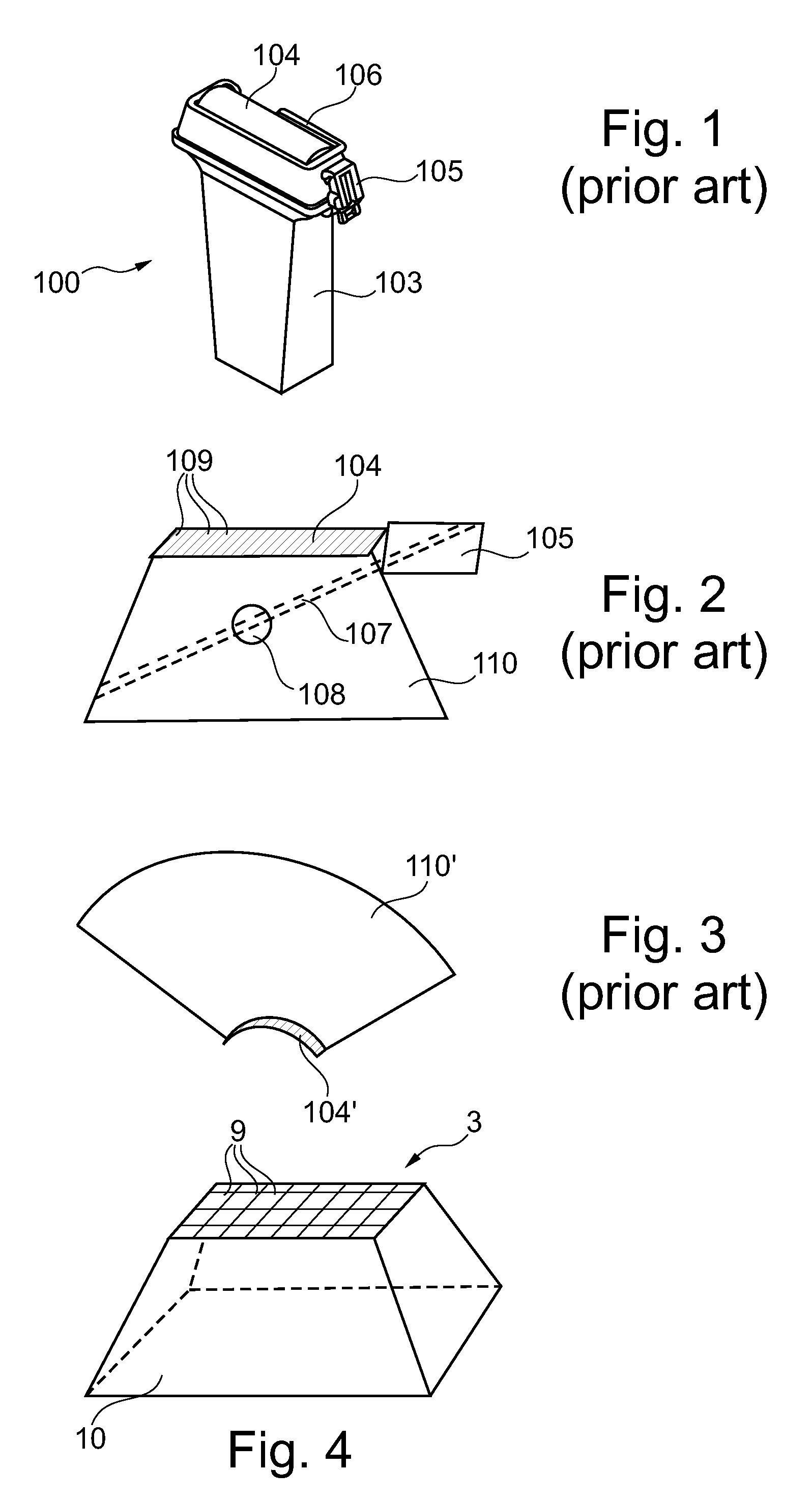
[0052]The conventional biopsy guide system 100 shown in FIG. 1 comprises a 1D ultrasound transducer 103. A biopsy guide bracket 106 is arranged around the transducer face 104. In an azimuthal position with respect to the longitudinal transducer face 104, a biopsy needle guide 105 is attached to the biopsy guide bracket 106. As indicated in FIG. 2, the ultrasound transducer 103 with the one-dimensional transducer face 104 is adapted to acquire an image from within a trapezoidal region included in an image plane 110 coinciding with and orthogonal to the transducer face 104.

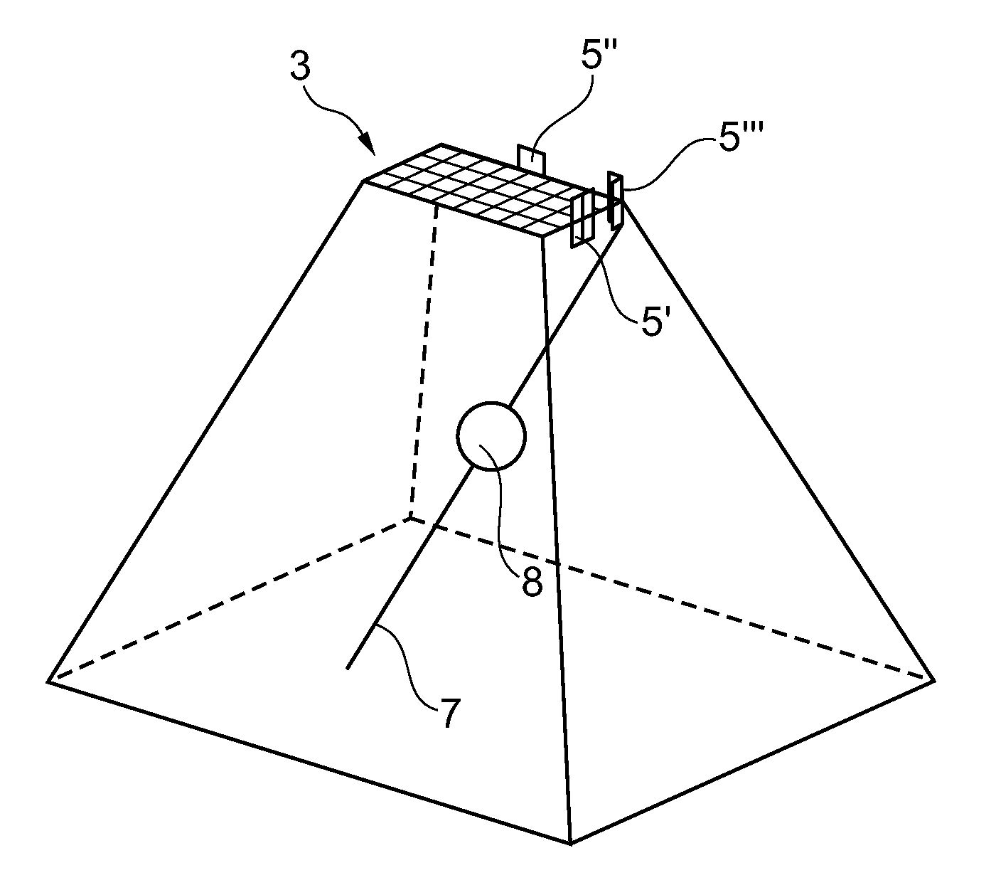
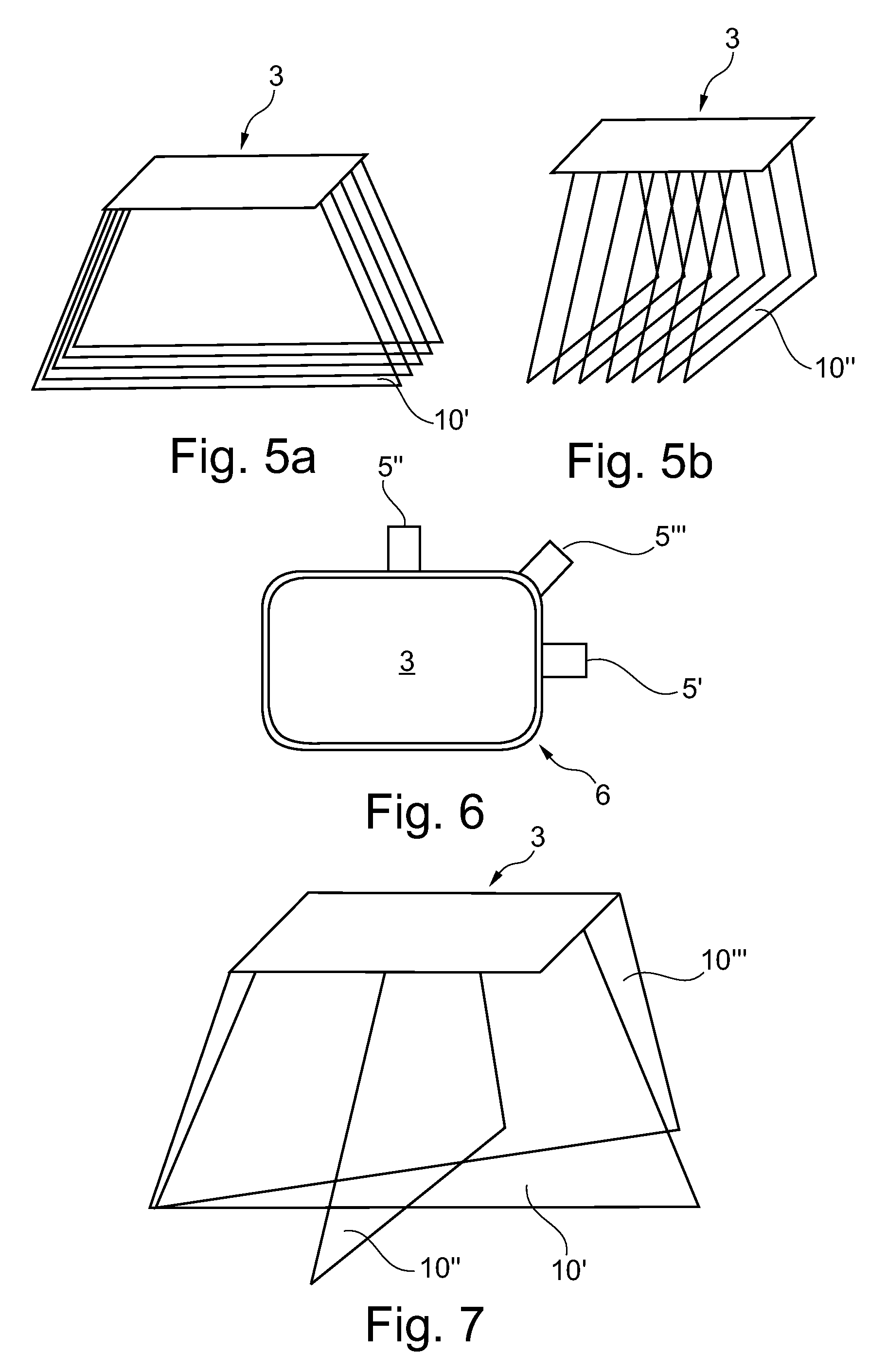
[0053]While with the conventional biopsy guide system shown in FIGS. 1 and 2 the image plane 110 has to be moved together with the biopsy guide system until it coincides with a region of interest 108 such that a biopsy needle may be guided along a biopsy path 107 using the biopsy needle guide 105, FIG. 4 illustrates an advantage which may be obtained when using a two-dimensional matrix ultrasound transducer for the ...


PUM


Abstract

A multi-position biopsy guide system and a method of using such biopsy guide system is proposed. The biopsy guide system comprises a 2D matrix ultrasound transducer (3) and comprises at least one biopsy needle guide (5) adapted for guiding a biopsy needle along a biopsy path (7). Therein, the multi-position biopsy guide system is adapted to controllably guide the biopsy needle along biopsy paths at variable locations with respect to the 2D matrix ultrasound transducer. Preferably, a location of the biopsy needle guide (5) with respect to the matrix ultrasound transducer may be determined and an ultrasound image in an image plane aligned with a biopsy path corresponding to the determined location of the biopsy needle guide may be acquired. Thereby, a biopsy process may be monitored for various locations and orientations of a guided biopsy needle.

Description

[0001]This application claims the priority of international application no. PCT / IB2010 / 051782, filed Apr. 23, 2010, which claims the benefit of U.S. provisional application Ser. No. 61 / 173,285, filed Apr. 28, 2009.FIELD OF THE INVENTION[0002]The invention relates to a biopsy guide system for guiding a biopsy needle along a biopsy path while monitoring with an ultrasound transducer. Furthermore, the invention relates to a method of controlling guidance of a biopsy needle using such biopsy guide.BACKGROUND OF THE INVENTION[0003]A biopsy is a medical test involving the removal of cells or tissues from a region of interest such as a lesion for medical examination purposes. The removed cells or tissues may be examined in order to detect the presence or extent of a disease.[0004]For removing the cells or tissues, a biopsy needle has to be introduced into a patient's body and has to be guided to the region of interest. In order to enable monitoring of the introduction and guidance of the b...

Claims


Application Information

Patent Timeline
Patent Type & Authority Patents(United States)
IPC IPC(8): A61B10/02G01S7/52A61B17/34A61B8/14G01S15/89A61B8/08
CPCA61B17/3403A61B8/0841A61B8/483G01S7/52074G01S7/52073G01S15/8993A61B8/0833A61B2017/3413
Inventor ROBINSON, ANDREW LEE
Owner KONINK PHILIPS ELECTRONICS NV
Why Eureka
Try Eureka