
Full-automatic fishing rod with assisting power triggering device

A trigger device and fully automatic technology, applied in fishing rods, fishing, applications, etc., can solve the problems of large resistance, insensitivity, and inability to retract, and achieve the effects of uniform distribution of elastic force, good stability, and good visibility

Inactive Publication Date: 2011-06-15
吴道顺
View PDF6 Cites 1 Cited by
  • Summary
  • Abstract
  • Description
  • Claims
  • Application Information

AI Technical Summary

Problems solved by technology

After throwing food into the water, there are many and cumbersome steps to fix the fishing rod to the rod frame. The design of the pull wire trigger mechanism is unreasonable, the resistance is large, insensitive, and the applicability is poor. The probability of running fish is very high; and the risk of being pulled overboard and irrecoverable

Method used


Image

  • Full-automatic fishing rod with assisting power triggering device
  • Full-automatic fishing rod with assisting power triggering device
  • Full-automatic fishing rod with assisting power triggering device

Examples


Embodiment 1

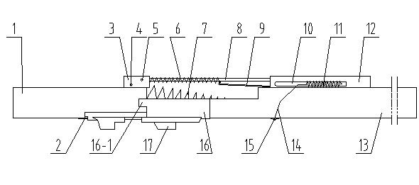
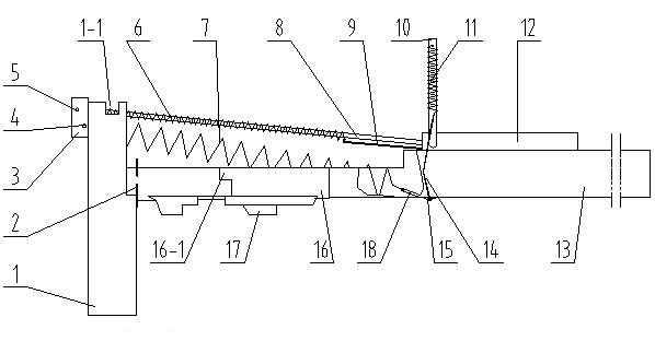
[0022] A fully automatic fishing rod with a power-assisted trigger device, which is connected by a fixed rod 1 and a moving rod 13, and the square boss 16-1 on the interlocking piece 16 at the rear of the moving rod is inserted into the square groove 1 on the fixed rod -1 is interlockingly connected, and at the same time relies on the positioning piece 2 on the fixed rod to form an integral body under the tension of the spring.

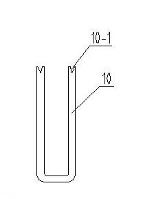
[0023] The fixed rod is a circular tube, and a square interlocking groove 1-1 is arranged axially symmetrically on the front end surface of the fixed rod. The positioning piece 2 is welded firmly below the fixed rod and stretches out the front end face of the fixed rod forward, and the fixed rod and the moving rod are connected as a whole to play a positioning effect, and as a fulcrum and a guide rail that the moving rod rotates during use. The shaft seat 3 is a square frame, which is firmly welded on the upper end of the fixed rod and exceeds the fro...

Embodiment 2

[0029] The kinetic energy storage support and power-assisted trigger mechanism are also composed of trigger rod, trigger rod positioning piece, trigger rod, trigger spring, strut, strut sheath, positioning connecting piece, strut guide spring and other parts. The structure and implementation Example 1 is the same. It is just that the moving rod is changed into the rod barrel 21, the fixed rod is changed into an inverted U-shaped support 19, a group of kinetic energy springs 7 is added, and there is also an arc-shaped rod-holding piece 20 that can clamp the fishing rod. The arc-shaped rod-holding piece is formed by The upper and lower pieces form a duckbill shape, the lower curved piece is integrated with the rod holder, the upper curved piece is connected with the U-shaped bracket and the rod holder at the front end through the positioning pins on both sides, and the two sides of the rear end are respectively Connect one end of the kinetic energy spring, and the other end of t...


PUM


Abstract

The invention discloses a full-automatic fishing rod with an assisting power triggering device, which is provided with a kinetic energy storage support rod and an assisting power triggering mechanism, wherein the support rod and the triggering mechanism are arranged at the upper part of the fishing rod, so a user can obtain great visibility, flexible triggering and easy operation; the full-automatic fishing rod can be used together with various modes of handspikes, sea fishing rods or shore fishing rods, and is not only an eye-pleasing full-automatic fishing rod with bidirectional assisting power triggering, but can also be made into an individual fishing rod; the fishing effect of the fishing rod rivals that of the Taiwan fishing method owing to the assisted power in both pulling triggering and returning triggering; and the full-automatic fishing rod also has the function of automatic rod holding.

Description

Technical field: [0001] The invention relates to a fully automatic fishing rod with a booster trigger device. Background technique: [0002] Sea fishing rods, rocky fishing rods, long-range throwing rods, front-casting rods, etc. are commonly used fishing equipment. They are used in conjunction with traditional rod holders during fishing, and their status is fixed. In order to make these rods have automatic fishing functions, people have not stopped. The pace of research and development. Before this patent application, there have been a variety of integrated automatic sea rods or automatic sea rod racks used in conjunction with traditional sea rods. Most of them are triggered by pull wires. After throwing food into the water, there are many and cumbersome steps to fix the fishing rod to the rod frame. The design of the pull wire trigger mechanism is unreasonable, the resistance is large, insensitive, and the applicability is poor. The probability of running fish is very hig...

Claims


Application Information

Patent Timeline
Patent Type & Authority Applications(China)
IPC IPC(8): A01K87/02
Inventor 吴道顺
Owner 吴道顺
Learn More