
Method for arranging wind power generation equipment in shallow water of intertidal zone

A technology of wind power generation equipment and installation method, which is applied to wind turbine components, wind energy power generation, wind turbines, etc., can solve problems such as difficulties, inability to enter the construction site for land installation equipment, and inability to enter the construction site, and achieves high installation efficiency. Effect

Inactive Publication Date: 2011-06-15
DALIAN HUARUI HEAVY IND GRP CO LTD
View PDF6 Cites 7 Cited by
  • Summary
  • Abstract
  • Description
  • Claims
  • Application Information

AI Technical Summary

Problems solved by technology

In areas below this limit or even shallower water depth, conventional land-installed equipment cannot enter the site for construction due to geological conditions in the intertidal zone, and offshore lifting equipment that meets the requirements for wind turbine installation is also unable to enter the site for construction due to limited draft conditions
For the intertidal zone with a water depth of 2m and below, the transportation, hoisting and installation of wind turbine equipment is particularly difficult. Therefore, a wind power installation method for the intertidal zone with a water depth of 2m and below is designed and invented to achieve reliable, efficient and fast installation of wind power equipment. Become an urgent technical problem to be solved

Method used


Image

  • Method for arranging wind power generation equipment in shallow water of intertidal zone
  • Method for arranging wind power generation equipment in shallow water of intertidal zone
  • Method for arranging wind power generation equipment in shallow water of intertidal zone

Examples


Embodiment 1

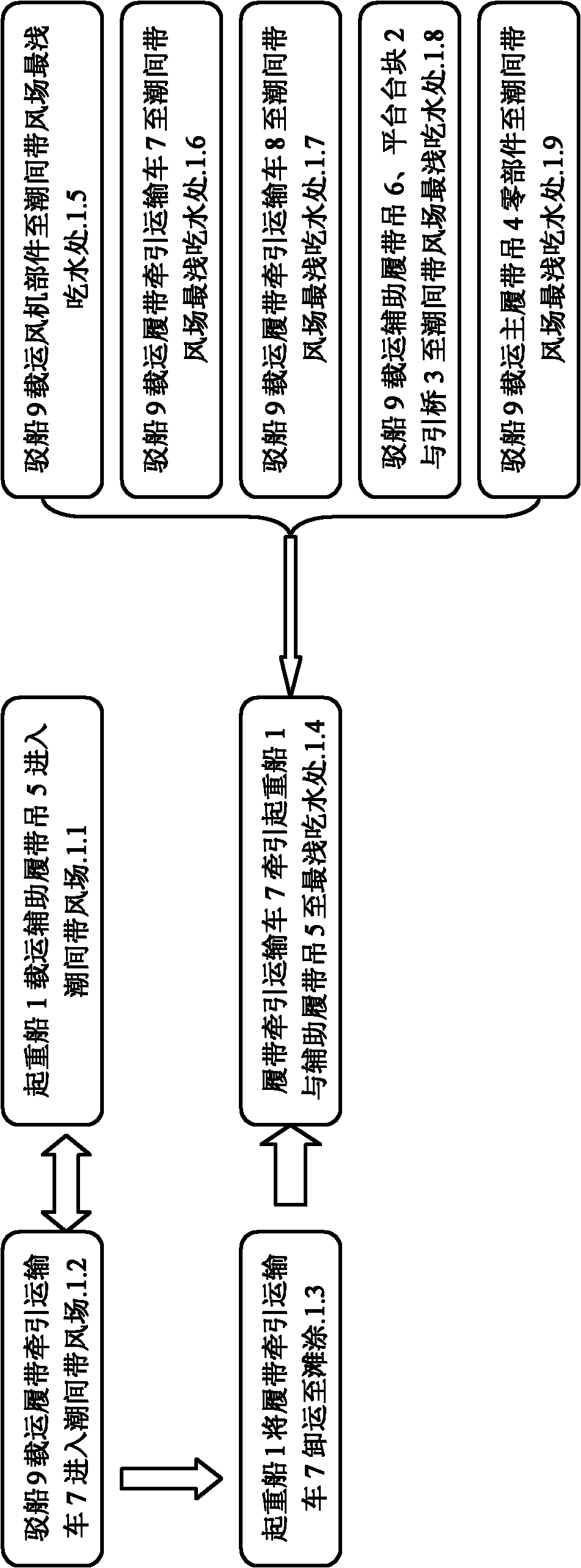
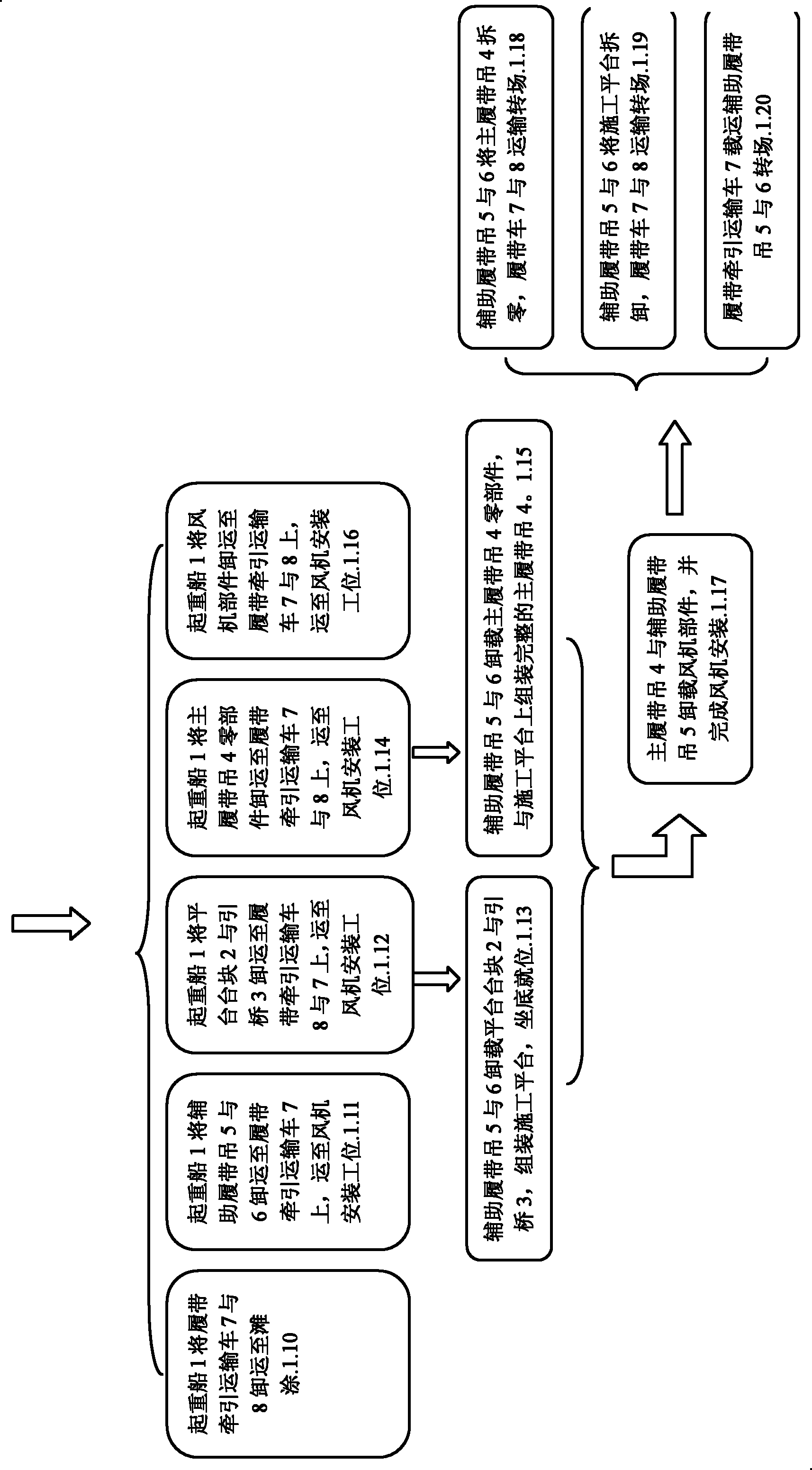
[0046] A construction method for transporting and installing wind power generation equipment in an intertidal zone with a water depth of 2m or less, characterized in that it includes the following steps:

[0047] (1) Crane ship 1 carries 260t auxiliary crawler crane 5 into the intertidal zone wind field by external force;

[0048] (2) The barge 9 carries the 150t crawler tractor transport vehicle I7 into the wind field in the intertidal zone, and berths the crane ship 1;

[0049] (3) The crane ship 1 unloads the 150t crawler tractor transport vehicle I7 onto the tidal flat;

[0050] (4) 150t crawler traction transport vehicle I7 tow crane ship 1 and 260t auxiliary crawler crane 5 to the shallowest draft;

[0051] (5) The barge 9 carries the wind turbine components to the shallowest draft of the wind field in the intertidal zone, and the 150t crawler tractor transport vehicle I7 tows the transport barge 9 to berth the crane ship 1;

[0052] (6) The barge 9 carries some 150t c...


PUM


Abstract

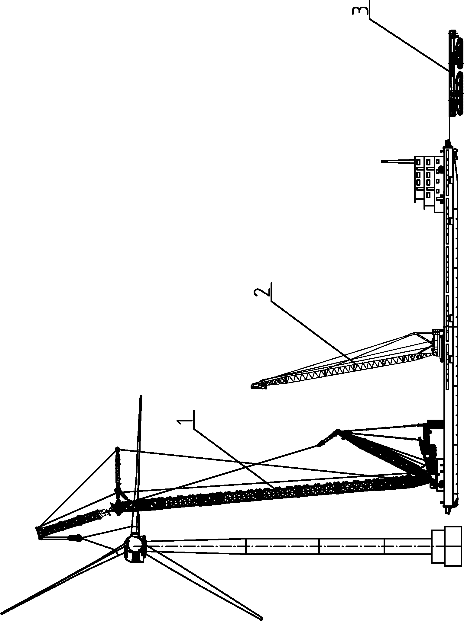
The invention discloses a method for arranging wind power generation equipment in the shallow water of an intertidal zone, which aims to solve the problems of equipment arrangement by adopting a construction method skillfully combining tracked carriers, crawler cranes, a crane ship, a barge and the like. The method is characterized by comprising the following steps that: the crane ship carries anauxiliary crane, and automatically voyages to a position with the smallest draught; the barge transports equipment comprising fan parts, the tracked carriers, platform blocks, approach bridges, a main crawler crane, an auxiliary crawler crane and the like to the position with the smallest draught; the tracked carriers transport the fan parts, the platform blocks, the approach bridges and the maincrawler crane part to a fan mounting station; the auxiliary crawler crane finishes the assembly of a construction platform at the fan mounting station and the complete main crawler crane; the main crawler crane and the auxiliary crawler crane finish the assembly and hoisting of the fan parts; and after the steps are finished, the auxiliary crawler crane disassembles the main crawler crane and theconstruction platform to a transportable weight, and the tracked carriers transport the main crawler crane and the construction platform to the next fan mounting station.

Description

Technical field: [0001] The invention relates to a method for installing wind power generation equipment, especially the wind power generation equipment in the intertidal shallow water area. Background technique [0002] my country is rich in offshore wind energy resources and has the conditions for large-scale development. The intertidal wind turbine installation technology is an international technical problem that restricts the development of offshore wind power. At present, there is no mature solution, especially for wind power installation methods in shallow water areas. The water depth in the area where wind turbines are installed in the intertidal zone in China is 3.5m, which is the shallowest water area in the intertidal zone that can meet the needs of wind power installation equipment, and the number of suitable equipment is extremely limited. In areas below this limit or even shallower water depths, conventional land-mounted equipment cannot enter the site for con...

Claims


Application Information

Patent Timeline
IPC IPC(8): B66C23/52F03D11/00
CPCY02E10/722Y02E10/72
Inventor 籍波邹胜吕新民黄有方高飞郭春晓王志良王强
Owner DALIAN HUARUI HEAVY IND GRP CO LTD
Learn More