Method for keeping high precision of real time clock circuit
A real-time clock, high-precision technology, applied in the field of communications, can solve problems such as reduced accuracy, inability to continuously adjust deviations, and inability to solve real-time clock circuit deviations in real time, so as to ensure accuracy and shorten service time.
Active Publication Date: 2011-06-15
NO 54 INST OF CHINA ELECTRONICS SCI & TECH GRP
View PDF1 Cites 8 Cited by
- Summary
- Abstract
- Description
- Claims
- Application Information
AI Technical Summary
Problems solved by technology
Generally, the real-time clock circuit is provided with an oscillating circuit to generate a clock. Due to circuit aging, crystal aging or the characteristic change of the clock element due to temperature changes, the output time information gradually shifts. The real-time clock circuit of the prior art utilizes the real-time clock circuit The error information of the clock component is set internally, and the time of misshift after a certain period of time is periodically predicted and compensated instead of using the standard clock calibration. This can neither solve the deviation in the real-time clock circuit in use in real time, nor The deviation cannot be adjusted continuously, and the error information that appears through prediction itself has the problem of gradually decreasing accuracy
Method used
View moreImage
Smart ImageViewing Examples
Examples
Embodiment Construction
Login to View More PUM
 Abstract
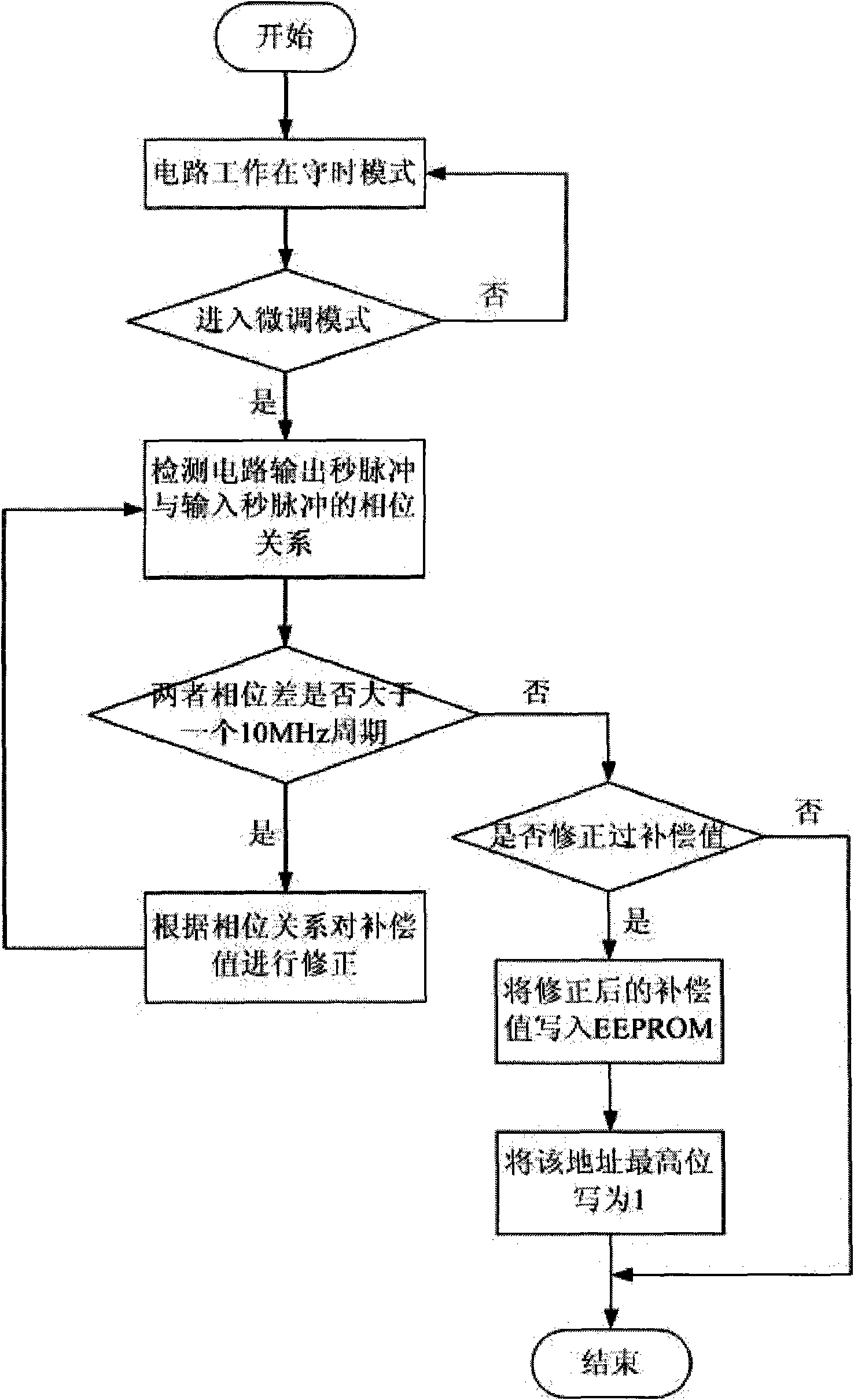
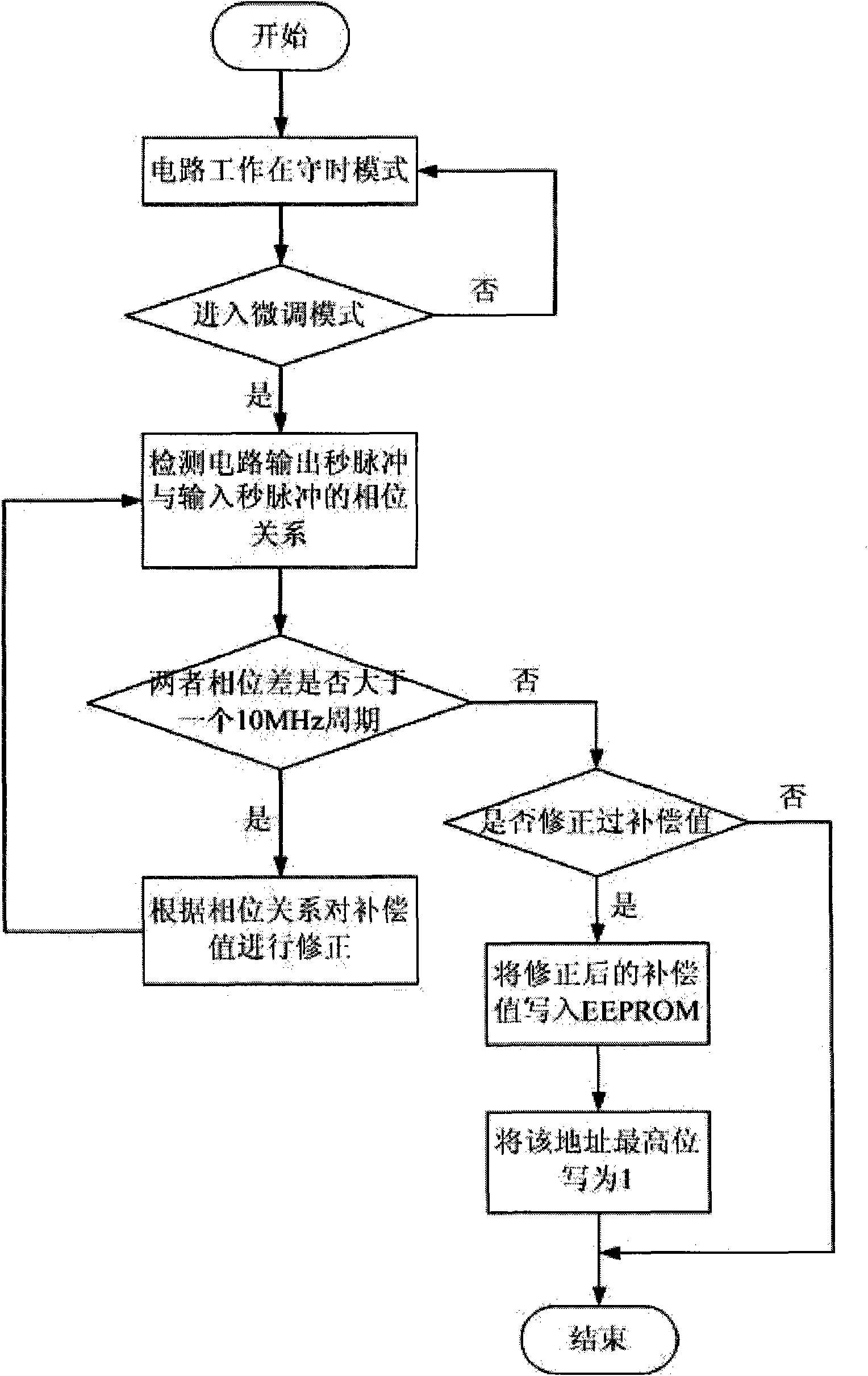
The invention discloses a method for keeping the high precision of a real time clock circuit, and relates to the correction technology in the field of a real time clock. Aiming at the frequency shift caused by the circuit aging, the crystalloid aging and the like when the real time clock circuit is used, the method is used for adjusting an oscillation circuit of the real time clock circuit according to the deviation between the input standard second pulse and the output second pulse generated by the real time clock circuit to lead the real time clock circuit to be always kept at a high precision. The method has the advantages that the real time clock circuit can be automatically adjusted in the normal use, the manual maintenance time and cost are reduced, and the circuit is kept at the high precision and the exact time, thereby being particularly suitable for the real time clock circuit used in navigation equipment.
Description
A Method of Keeping High Precision of Real Time Clock Circuit technical field The invention relates to a method for maintaining the high precision of a real-time clock circuit in the field of communication. More specifically, it is a method for automatically compensating the error of the real-time clock over time. It is especially suitable for communication devices requiring high-precision punctuality , satellite navigation and other equipment. Background technique When the communication terminal moves, except for mobile communication systems such as CDMA and GSM that can receive standard time information through satellites, since standard time information cannot be received from satellites, it is equipped with a real-time clock circuit and constitutes a The clock function of the mobile communication terminal. Generally, the real-time clock circuit is provided with an oscillating circuit to generate a clock. Due to circuit aging, crystal aging or the characteristic chang...
Claims
Login to View More Application Information
Patent Timeline
 Patent Type & Authority Applications(China)
IPC IPC(8): G06F1/14
Inventor 李斌田素雷周永川王天彪马迅李军佑
Owner NO 54 INST OF CHINA ELECTRONICS SCI & TECH GRP
Features
- R&D
- Intellectual Property
- Life Sciences
- Materials
- Tech Scout
- Unparalleled Data Quality
- Higher Quality Content
- 60% Fewer Hallucinations
Learn More Browse by: Latest US Patents, China's latest patents, Technical Efficacy Thesaurus, Application Domain, Technology Topic, Popular Technical Reports.
© 2025 PatSnap. All rights reserved.Legal|Privacy policy|Modern Slavery Act Transparency Statement|Sitemap|About US| Contact US: help@patsnap.com


