Virtual private topology control method, device and system

A technology of virtual private network and topology control, applied in the field of communication, can solve the problems of wasting network resources, ambiguity, waste of network resources, etc., and achieve the effect of saving network resources and realizing control

Active Publication Date: 2011-06-15
上海源慧信息科技股份有限公司
View PDF3 Cites 16 Cited by
  • Summary
  • Abstract
  • Description
  • Claims
  • Application Information

AI Technical Summary

Problems solved by technology

[0005] In the process of realizing the above virtual private network topology control, the inventors found that at least the following problems exist in the prior art: because the PE at the source end of the sending message does not know whether the PE at the destination end has a root (root) port
When there is no root port at the destination end of the packet, and the source port of the packet is also a leaf port, the packet will be discarded at the destination PE, but the packet is still transmitted on the network, resulting in a waste of network resources.
In practical applications, the number of root ports is small, and many PEs only have leaf ports. This kind of waste of network resources is more prominent.

Method used


Image

  • Virtual private topology control method, device and system
  • Virtual private topology control method, device and system
  • Virtual private topology control method, device and system

Examples


Embodiment 1

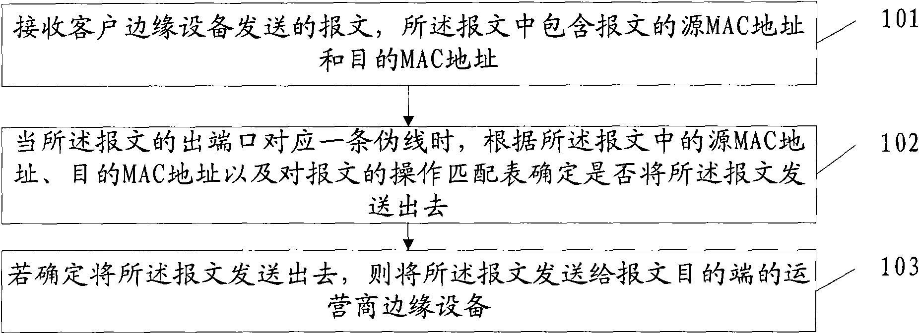
[0043] An embodiment of the present invention provides a virtual private network topology control method, such as figure 1 As shown, the method includes:

[0044] 101. Receive a packet sent by a client edge device, where the packet includes a source MAC address and a destination MAC address of the packet.

[0045] 102. When the egress port of the message corresponds to a pseudowire, determine whether to send the message according to the source MAC address, the destination MAC address in the message, and the operation matching table for the message.

[0046] Wherein, the operation matching table for the message includes: an uplink access control list or a filtering table; the uplink access control list includes a message source MAC address, a destination pseudowire, a message destination MAC address, and an operation for matching a message ; The filtering table includes the message source port attribute, the destination pseudowire, the port attribute of the remote operator's e...

Embodiment 2

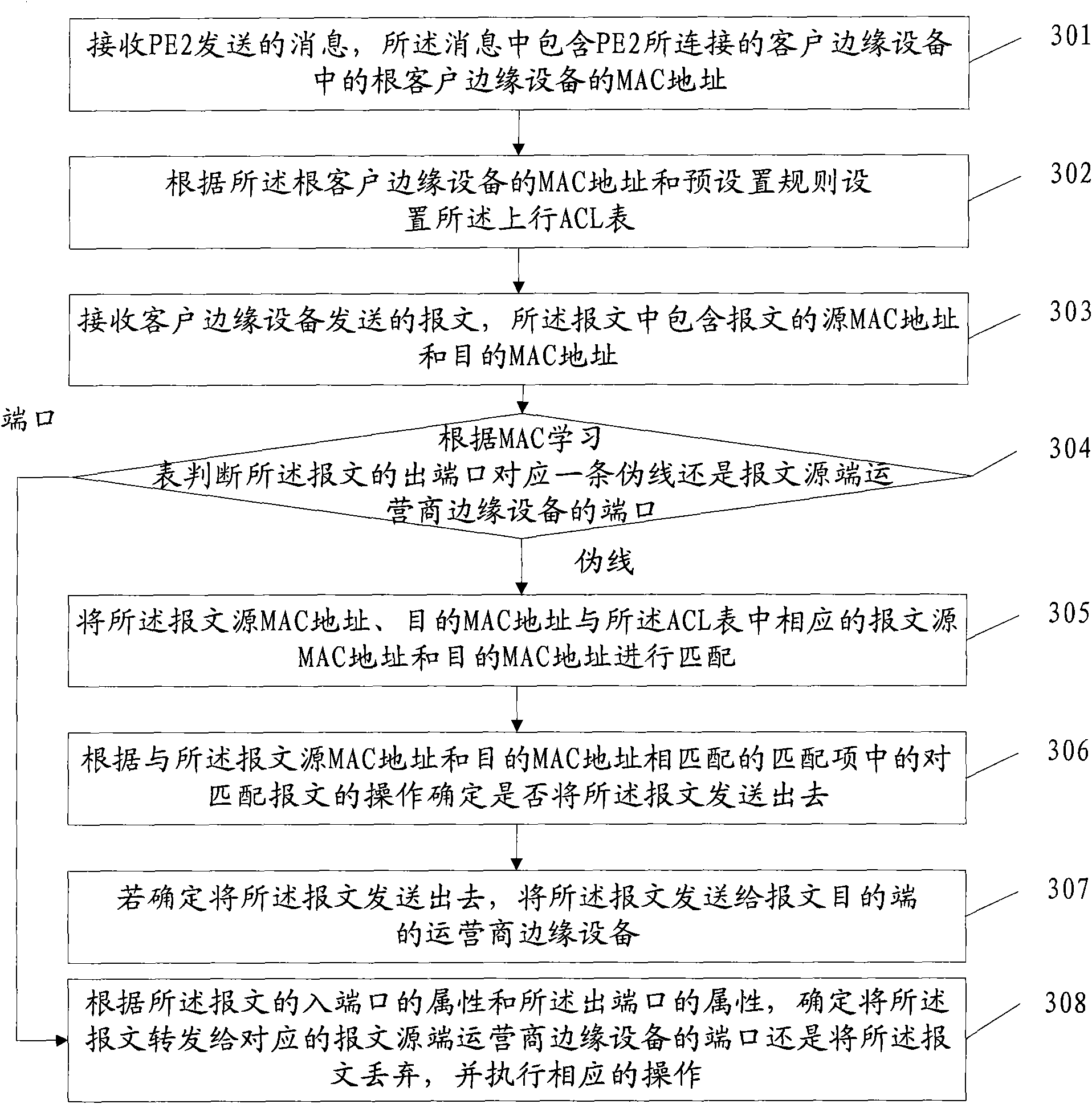
[0056] The embodiment of the present invention provides a virtual private network topology control method, the method is a message source end virtual private network topology control method, specifically, the message source PE (Provider Edge, operator edge equipment) according to the upstream ACL (Access Control List, access control list) determines whether to send out the virtual private network topology control method of the message, such as image 3 As shown, the method includes:

[0057] When implementing the embodiment of the present invention, it is first necessary to set up the uplink ACL table. After the uplink ACL table is set up, when the PE at the source end of the message receives the message sent by CE (Customer Edge, customer edge device), and determines When the outgoing port of the message is PW (Pseudo Wire, pseudowire), the PE at the source end of the message is based on the message source MAC address and message destination MAC address contained in the messa...

Embodiment 3

[0106] The embodiment of the present invention provides a virtual private network topology control method, the method is a virtual private network topology control method at the source end of the message, specifically, the PE (Provider Edge, operator edge device) at the source end of the message determines whether to The virtual private network topology control method that the message is sent out, such as Figure 8 As shown, the method includes:

[0107] When implementing the embodiment of the present invention, it is first necessary to set a filter table. After the filter table is set, when the PE at the source end of the message receives the message sent by CE (Customer Edge, customer edge device), and determines the When the outgoing port of the message is a PW (Pseudo Wire, pseudowire), the PE at the source end of the message is determined according to the message source MAC address contained in the message and the message destination MAC address and the filter table set ...


PUM


Abstract

The embodiment of the invention relates to the field of communication, and discloses a virtual private topology control method, a virtual private topology control device and a virtual private topology control system. The method comprises the following steps of: receiving a message transmitted by customer edge equipment, wherein the message comprises a source media access control (MAC) address anda destination MAC address of the message; when an out port of the message corresponds to a pseudo wire, determining whether to send the message out according to the source MAC address and the destination MAC address in the message and an operation matching table of the message; and if the message is determined to be sent out, sending the message to operator edge equipment at the destination end of the message. The method, the device and the system are mainly used in a process of the virtual private topology control, and can realize the virtual private topology control and simultaneously avoidsending an unnecessary message into a network, thereby saving network sources.

Description

technical field [0001] The invention relates to the communication field, in particular to a virtual private network topology control method, device and system. Background technique [0002] Traditional LANs use shared media to connect hosts, but some hosts that want to form a LAN are distributed in different regions, and these different regions are connected through a WAN (Wide Area Network, wide area network). In order to connect a group of site hosts distributed in different regions, there is a need to use WAN to virtualize a local area network. A VPN (Virtual Private Network, Virtual Private Network) technology was proposed thereupon. VPLS (Virtual Private LAN Service, virtual private LAN service) is to use the shared communication network to provide virtual Ethernet local area network services. ) is a service that allows users to simultaneously access the network from multiple geographically dispersed points and access each other, just as these points are directly conn...

Claims


Application Information

Patent Timeline
Patent Type & Authority Applications(China)
IPC IPC(8): H04L12/46H04L12/24
Inventor 江元龙黄勇
Owner 上海源慧信息科技股份有限公司
Why Eureka
Try Eureka