Eureka AIR delivers breakthrough ideas for toughest innovation challenges, trusted by R&D personnel around the world.

Multipurpose capsule

A multi-purpose, capsule technology, applied in the directions of transportation and packaging, can solve the problems of incomplete brewing of coffee powder, waste of resources, etc., and achieve the effects of simple and reasonable structure, good sealing performance and low production cost

Active Publication Date: 2011-06-22
GUANGDONG XINBAO ELECTRICAL APPLIANCES HLDG CO LTD
View PDF4 Cites 5 Cited by
  • Summary
  • Abstract
  • Description
  • Claims
  • Application Information

AI Technical Summary

Problems solved by technology

This structure uses built-in filter paper to form back pressure, which replaces the traditional micro-filter plus back pressure device, which effectively saves production costs, but it usually cannot completely brew the coffee powder in the capsule, resulting in a waste of resources

Method used


Image

  • Multipurpose capsule
  • Multipurpose capsule
  • Multipurpose capsule

Examples


no. 1 example

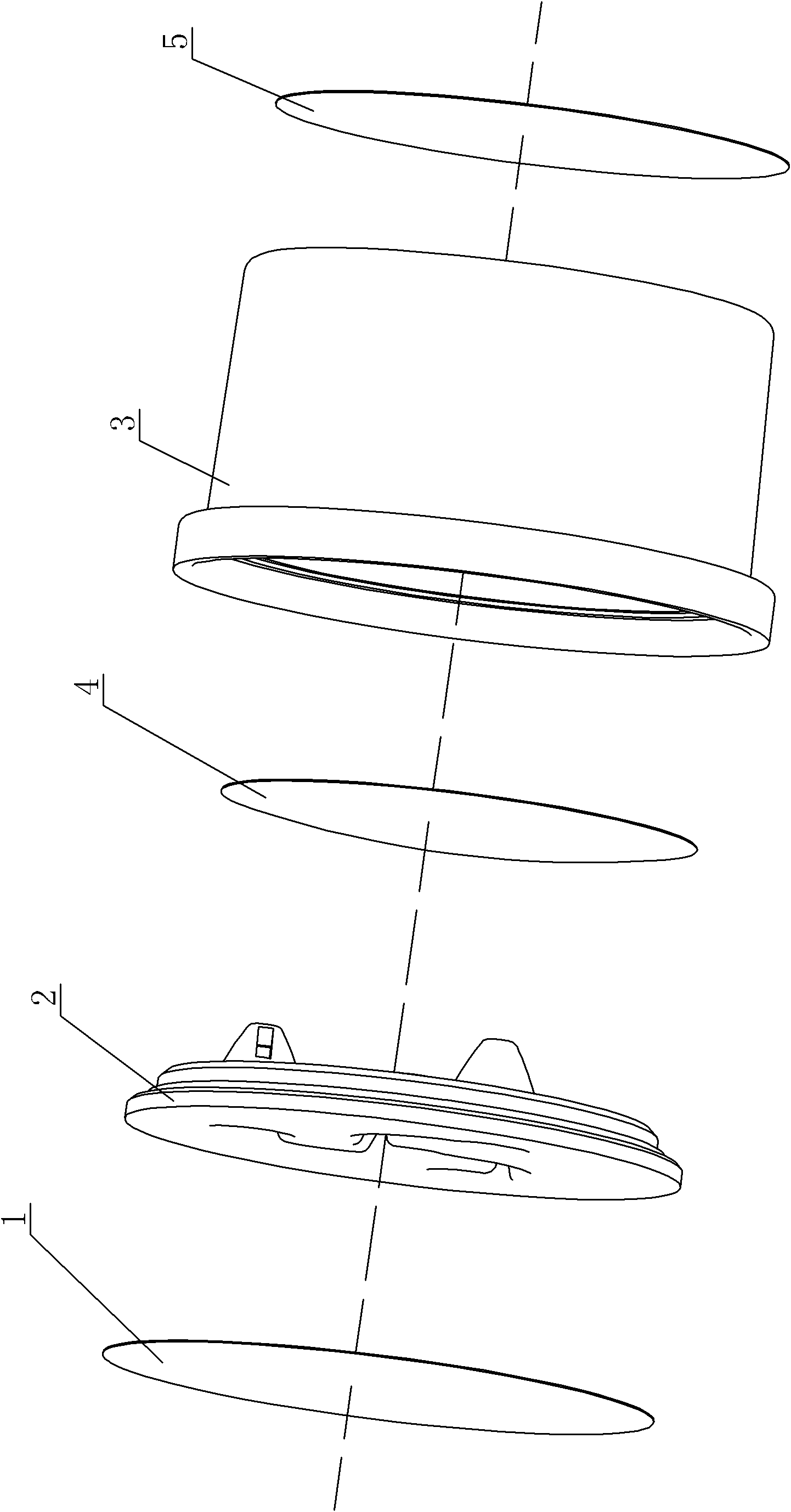
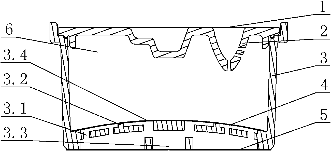
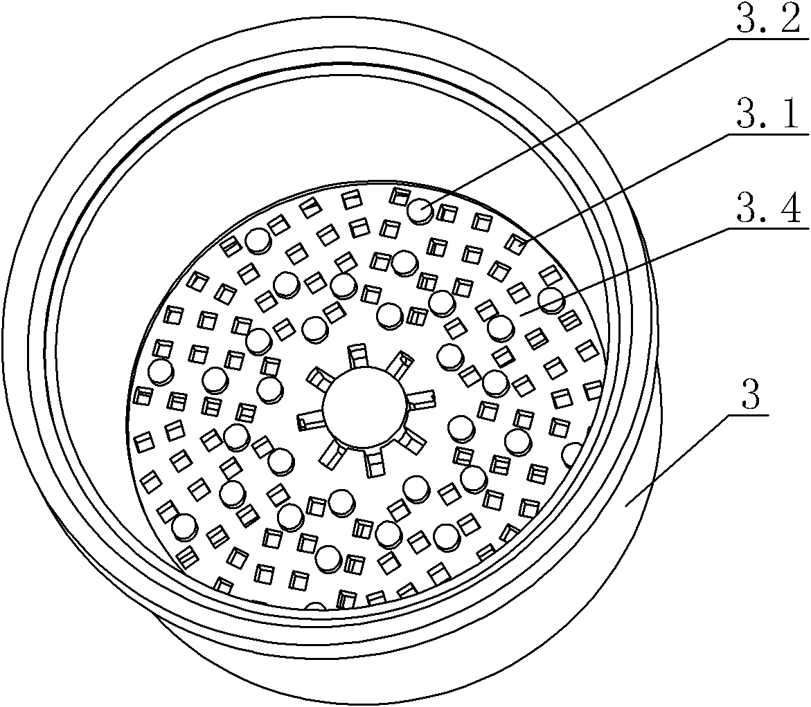
[0022] see Figure 1-Figure 4 , The multi-purpose capsule includes a capsule body 3 and a capsule cover 2 tightly covered thereon, both of which form a cavity 6, which can be used to hold coffee, tea leaves and the like for preparing beverages. The bottom of the capsule body 3 is provided with a water outlet 3.3, and the top of the capsule cover 2 is provided with a water inlet 2.3, and three flow channels 2.1 extend from the water inlet 2.3, and the flow channels communicate with the cavity 6.

[0023] see Figure 4 , the water inlet 2.3 is located at the top center of the capsule cover 2, and the water inlet 2.3 is radially provided with three arc-shaped flow channels 2.1 toward the outer edge of the capsule cover 2. Preferably, the three flow channels 2.1 are at 120 degrees Included angle, the end of the flow channel 2.1 communicates with the cavity 6 by setting the capsule water inlet 2.2. Its runner 2.1 can adopt inline shape, or wave shape, or right angle shape. The f...

no. 2 example

[0027] see Figure 5 , this multi-purpose capsule, its capsule cover 2 is compared with the first embodiment, and the main difference is that it is set on the capsule water inlet 2.2 and the shower hole 2.22 with smaller aperture and more holes is connected with the cavity 6, and the shower hole 2.22 Compared with the brewing hole 2.21, when the former is working, the sprayed water flow column is more, denser, and wider in range, and the contact with the brewing material in the capsule main body 3 is more sufficient, so that the brewing is more sufficient. Its flow channel 2.1 can adopt inline shape, wave shape, or right angle shape. Other unmentioned parts are the same as the first embodiment.

no. 3 example

[0029] see Image 6 , this multi-purpose capsule, its capsule cover 2 compares first embodiment, and main difference is that its water inlet end 2.3 is positioned at one side of capsule cover 2; The one-shaped flow channel 2.1, the angle between the flow channels 2.1 is 60 degrees, the flow channel 2.1 can disperse the water flowing through the water inlet 2.3 into multiple streams, and set the water inlet 2.2 of the capsule with a smaller aperture, The shower holes 2.22 with more holes are injected into the cavity 6 . It enters water from one side of the capsule cover 2, so that when brewing, the brewed matter in the capsule main body 3 will be rolled by the washing of the water flow, so as to make the brewing more sufficient. The runner 2.1 can also be arc-shaped, wave-shaped, or right-angled. Other unmentioned parts are the same as the first embodiment.


PUM


Abstract

The invention discloses a multipurpose capsule, which comprises a capsule main body and a capsule cover which is tightly covered on the capsule main body, wherein a cavity is formed by the capsule main body and the capsule cover; the bottom of the capsule main body is provided with a water outlet hole; the top of the capsule cover is provided with a water inlet end; at least two flow channels extend from the water inlet end, and are communicated with the cavity; the water inlet end is positioned in the center of the top of the capsule cover; at least two flow channels are radially formed from the water inlet end to the periphery of the outer edge of the capsule cover; the water inlet end is positioned on one side of the capsule cover; at least two flow channels are formed from the water inlet end to the other side of the capsule cover radially like a trumpet; the tail end of each flow channel is communicated with the cavity by forming a capsule water inlet; and water flowing through the water inlet end can be dispersed into multiple strands of water current by the flow channels, and is injected into the cavity through infusion holes or shower head holes on the water inlet of the capsule. When hot water is poured into a beverage, a plurality of high-pressure water currents flow into the capsule, the contact surface between the multipurpose capsule and an brewed object (such as coffee, tea and the like) is increased simultaneously, so that brewing is more thorough.

Description

technical field [0001] The invention relates to a multipurpose capsule, in particular to a multipurpose capsule for brewing coffee or tea leaves. Background technique [0002] Traditional capsules such as coffee capsules generally use two micro-filters and back pressure devices in the upper and lower parts of the capsule. When water enters the capsule, it is first dispersed by the first layer of micro-pressurized filters and pressurized evenly to contact the coffee. The ground coffee is then passed through a second micro-filter counter-pressure device, allowing the coffee liquid to flow out of the capsule. The capsule of this structure has a complicated structure and high cost, and the coffee powder in the capsule is easy to flow out of the capsule. In order to solve the above problems, people have further improved the coffee capsules. For example, Chinese Patent Document No. CN201267357 disclosed a coffee capsule on July 8, 2009. A through hole, a ring body is fixed on th...

Claims


Application Information

Patent Timeline
IPC IPC(8): B65D85/808
Inventor 郭建刚陈光华曾永春
Owner GUANGDONG XINBAO ELECTRICAL APPLIANCES HLDG CO LTD
Why Eureka
Eureka Blog
Learn More