Pneumatic spiral direction-converted conveyor

A conveyor and steering technology, applied in the field of direction conversion devices, can solve problems such as unbalance, surrounding sinking, adverse effects of glass plates, etc., and achieve the effect of improving the quality of processed products

Inactive Publication Date: 2011-06-22
TAE SUNG ENG
View PDF6 Cites 2 Cited by
  • Summary
  • Abstract
  • Description
  • Claims
  • Application Information

AI Technical Summary

Problems solved by technology

[0010] In other words, as the specifications of flat-panel display devices increase in size, in order to reliably transfer and process large glass plates, and to accommodate large-size glass plates, it is necessary to increase the size of the steering gear; , when the upper frame moves up / down, due to the bending phenomenon of the upper frame, it will cause adverse effects on the transferred glass plate
[0011] That is to say, when the upper frame rises through the upper / lower cylinder installed in the central part, the pressure acts on the central part concentratedly, which will cause the peripheral sinking phenomenon
[0012] At the same time, when transferring large-sized glass plates, the discharge rollers arranged on the upper frame should form a uniform plane at the same height, while the central part is high and the surroundings are in a state of sinking, forming an imbalance that will give the glass plates cause adverse effects

Method used


Image

  • Pneumatic spiral direction-converted conveyor
  • Pneumatic spiral direction-converted conveyor
  • Pneumatic spiral direction-converted conveyor

Examples


Embodiment Construction

[0025] Exemplary embodiments of the present invention are described in detail in accordance with the following drawings.

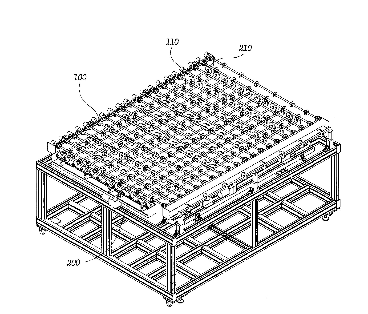
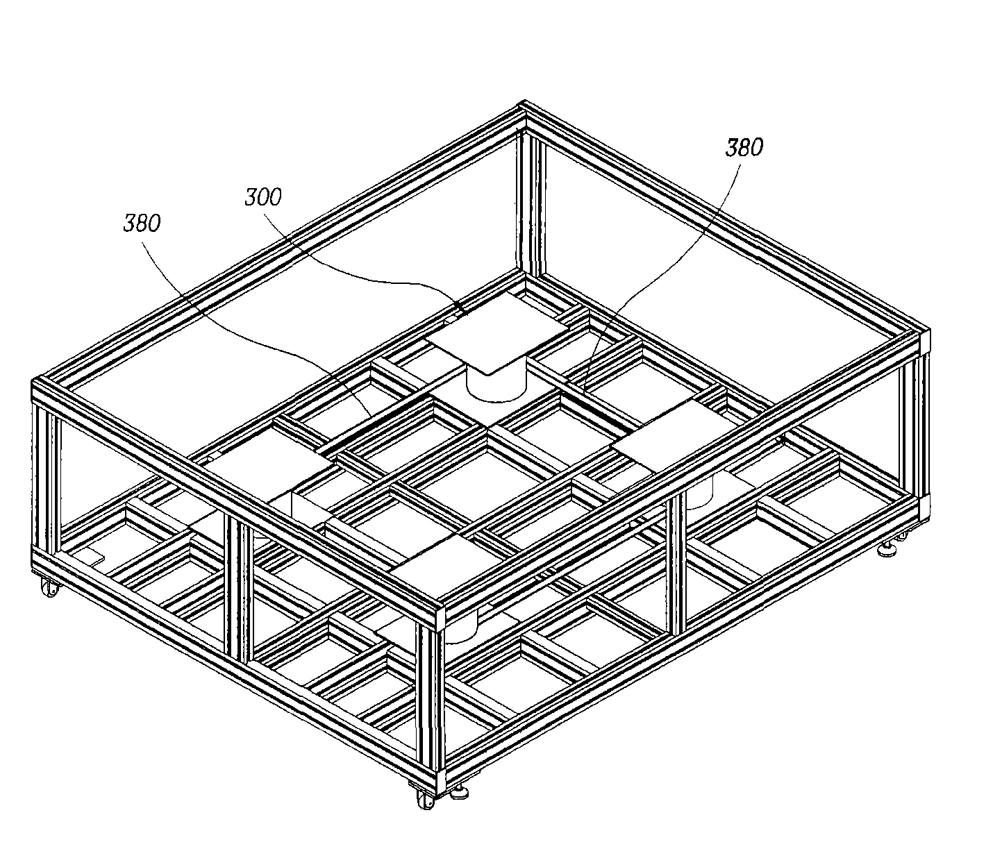
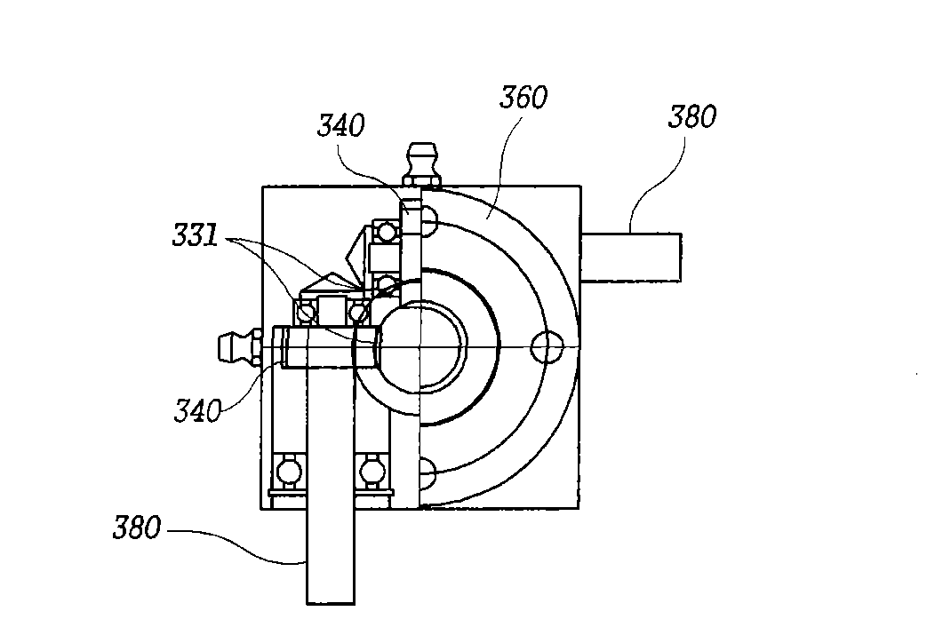
[0026] figure 1 is a perspective view showing the structure of the implementation case of the present invention; figure 2 is a perspective view showing the structure of the operating part of the present invention; FIG. 3 is a partial cross-sectional view showing the internal structure of the pneumatic spiral at the core of the present invention, Figure 3a is a plane cross-sectional view, Figure 3b is a frontal cross-sectional view; Figure 4 Yes figure 1 the floor plan;

[0027] The present invention is composed of a lower frame 100, an upper frame 200 and a plurality of pneumatic screws 300. The upper frame 200 plays a lifting role relative to the above-mentioned lower frame 100 at a certain height, and the plurality of pneumatic screws and the above-mentioned upper frame 200 keep balance , can realize the lifting effect.

[0028] The above-menti...


PUM


Abstract

The invention relates to a technology of a direction conversion device of a manufacturing engineering conveyor line of a glass plate for a liquid crystal display device, in particular to a pneumatic spiral direction-converted conveyor. In order to more stably convert the conveying direction of a heavy-weight large-size glass plate, a balanced level state is integrally kept by uniformly dispersingpower in the ascending / descending action process of an upper stand provided with trip rollers in an arraying way so that partial subsidence is not generated, therefore bad influence is ensured not tobe caused on the glass plate and the quality of processed products is also enhanced when the direction of the large-size glass plate is converted.

Description

technical field [0001] The present invention relates to a technology for manufacturing a direction converting device of a construction conveying line using glass plates for liquid crystal display devices. In more detail, it relates to a pneumatic helical steering type conveying device that can more stably change the conveying direction of large-weight and large-sized glass plates. machine. Background technique [0002] Generally speaking, the glass plate turning device can be divided into the following ways: the glass plate transferred to the worktable is run in the running direction or the transfer mode is changed in the vertical direction; the glass plate transferred to the worktable is moved according to the running direction. Orientation, or a steering method that moves in the desired direction after rotating in place; [0003] Among these steering devices, carefully observe the steering device of the rotating glass plate, there are a plurality of rotating shafts arrang...

Claims


Application Information

Patent Timeline
Patent Type & Authority Applications(China)
IPC IPC(8): B65G47/244B65G49/06
Inventor 柳津殖
Owner TAE SUNG ENG
Why Eureka
Try Eureka