Rotary compressor

A compressor and double-rotation technology, applied in the direction of rotary piston machinery, mechanical equipment, machines/engines, etc., can solve the problems of increased refrigerant leakage, compressor loss, etc., reduce the contact area, improve compression efficiency, The effect of reducing leakage

Active Publication Date: 2011-06-22
LG ELECTRONICS INC
View PDF5 Cites 8 Cited by
  • Summary
  • Abstract
  • Description
  • Claims
  • Application Information

AI Technical Summary

Problems solved by technology

However, when the height of the lower cylinder is high, the contact area between the rotary piston and the vane increases in the lowe

Method used


Image

  • Rotary compressor
  • Rotary compressor
  • Rotary compressor

Examples


Embodiment Construction

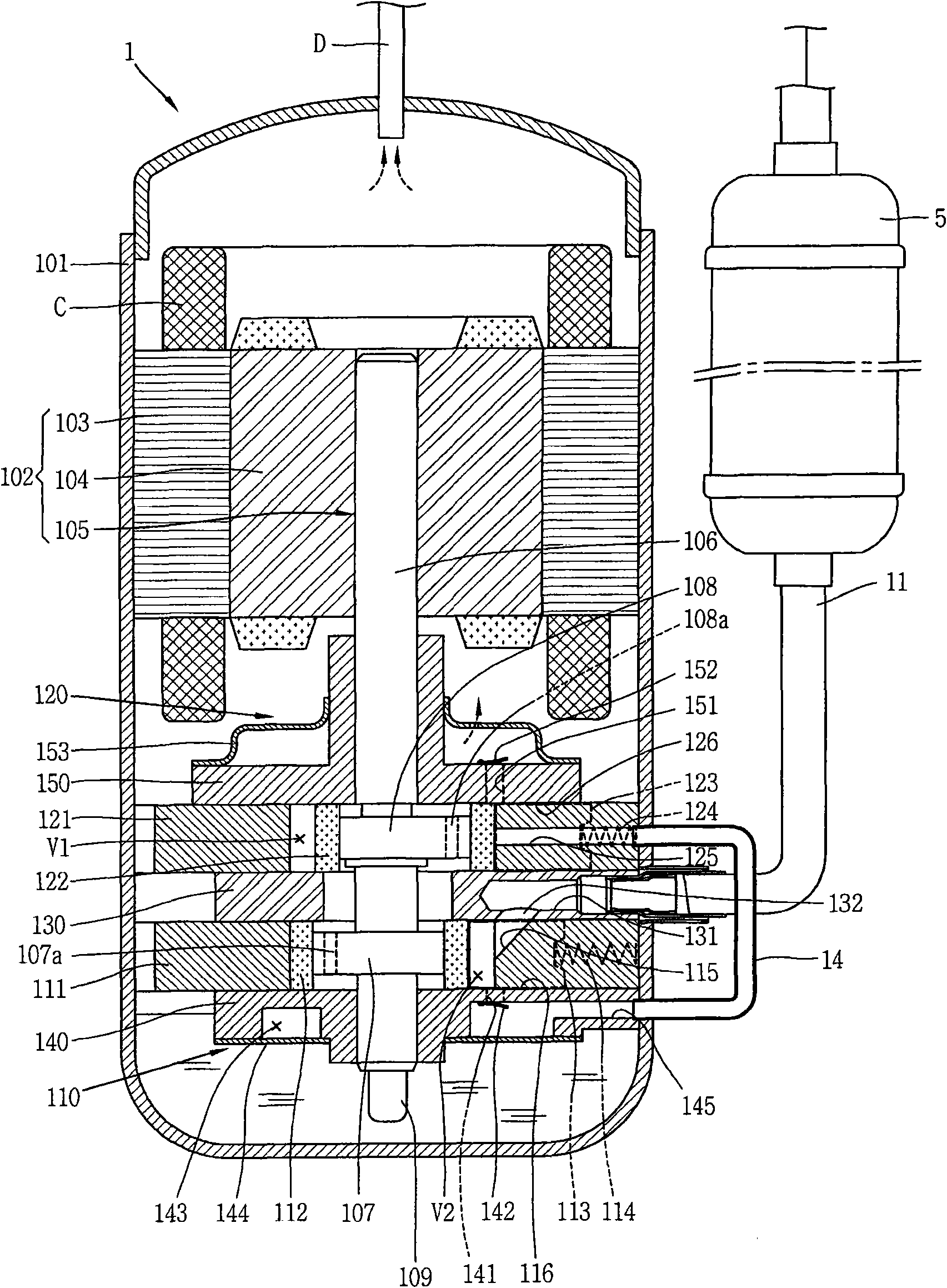
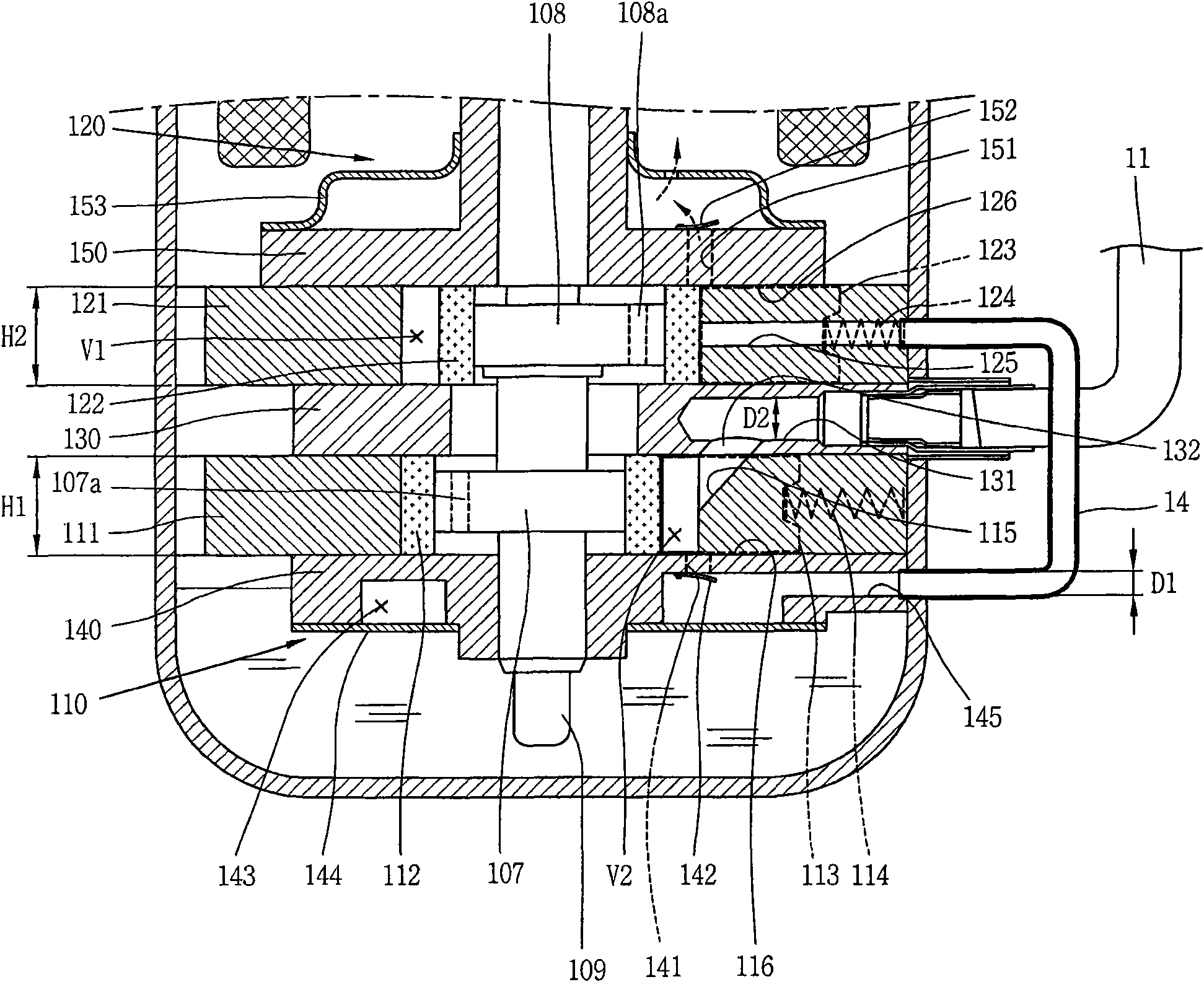
[0020] Details of a double rotary compressor according to an exemplary embodiment will now be described with reference to the accompanying drawings. For brief description with reference to the drawings, the same or equivalent components are given the same reference numerals, and their description will not be repeated.

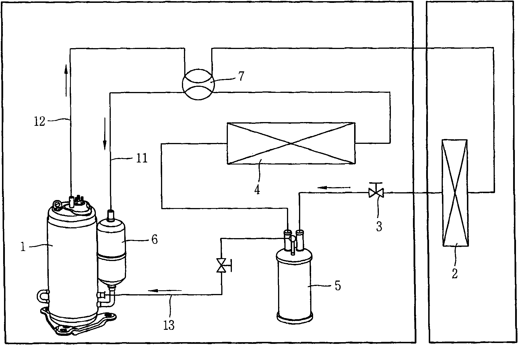
[0021] figure 1 is a schematic diagram showing a refrigeration cycle having a two-stage type rotary compressor for sequentially compressing refrigerant as one type of double rotary compressor according to an exemplary embodiment.

[0022] Such as figure 1 As shown, a refrigeration cycle having a two-stage type rotary compressor according to an exemplary embodiment may include components such as a compressor 1 , a condenser 2 , an expansion valve 3 , an evaporator 4 , and a phase separator 5 . The refrigerant compressed in the compressor 1 is introduced into the condenser 2 to exchange heat with surrounding air, thereby being condensed. The condensed refriger...


PUM


Abstract

A twin rotary compressor is provided. In the twin rotary compressor, a refrigerant suction pipe may be connected to a middle plate positioned between a first cylinder and a second cylinder to reduce a height of the first cylinder, so that heights of a first rolling piston and a first vane may also be lowered. This may allow a contact area between the first rolling piston and the first vane to be decreased so as to reduce refrigerant leakage from a first compression space of the first cylinder, resulting in improvement of compression efficiency of the compressor.

Description

technical field [0001] The invention relates to a double-rotary compressor with a plurality of compression spaces. Background technique [0002] Refrigerant compressors are generally used in refrigerators or air conditioners utilizing a vapor compression refrigeration cycle (hereinafter, referred to as "refrigeration cycle"), and constant-speed type compressors driven at a substantially constant speed and controllable rotation speeds have also been used. inverter compressor. [0003] The drive motor and the compressor controlled by the drive motor are installed in the inner space of the hermetic housing, which is called a hermetic compressor, and the refrigerant compressor whose drive motor is installed separately outside the housing is called an open compressor. . Most domestic or commercial refrigerators use hermetic compressors. Also, refrigerant compressors may be classified into reciprocating compressors, scroll compressors, rotary compressors, etc. according to diff...

Claims


Application Information

Patent Timeline
IPC IPC(8): F04C23/00
CPCF04C18/086F04C23/001F04C28/02F04C18/356F04C2240/80F04C29/12F04C23/008
Inventor 李允熙李承俊龙玟徹
Owner LG ELECTRONICS INC
Why Eureka
Try Eureka