Slide device for vehicle

A technology for sliding devices and vehicles, which is applied to special positions of vehicles, vehicle seats, vehicle components, etc., and can solve the problems of upper rails that hinder the front and rear movement, increase in size, and hinder the front and rear movement

Inactive Publication Date: 2011-06-22
AISIN SEIKI KK
View PDF6 Cites 3 Cited by
  • Summary
  • Abstract
  • Description
  • Claims
  • Application Information

AI Technical Summary

Problems solved by technology

However, since the slider is always in contact with the inner wall surface of the lower rail, when the upper rail is moved back and forth along the lower rail, sliding frictional resistance may be generated in the above-mentioned contact portion, preventing smooth back and forth movement.
Although the above-mentioned sliding frictional resistance can be eliminated by arranging rollers that contact in the vertical direction and the left-right direction between the upper rail and the lower rail, the device itself will increase in size and cost. When there is a deviation in the size of the rail, the metal roller cannot absorb the deviation, and as a result, the smooth forward and backward movement of the upper rail relative to the lower rail is hindered.

Method used


Image

  • Slide device for vehicle
  • Slide device for vehicle
  • Slide device for vehicle

Examples


Embodiment Construction

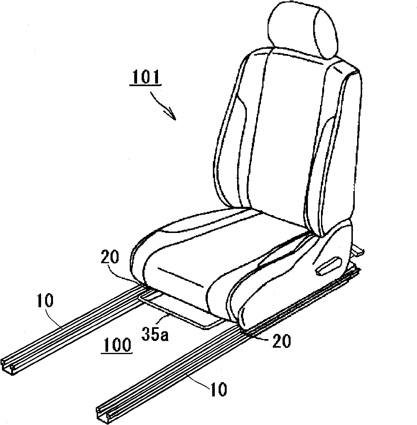
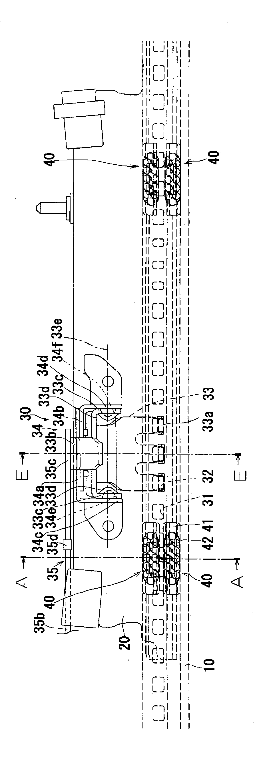
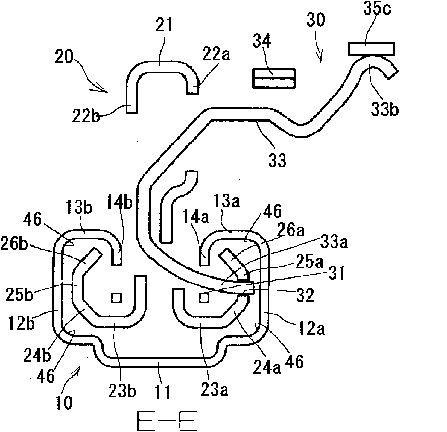
[0049] Next, a first embodiment of the sliding device for a vehicle according to the present invention will be described below with reference to the drawings. Such as figure 1 , figure 2 and Figure 7 As shown, the sliding device for a vehicle according to the first embodiment includes: a pair of lower rails (first rails) 10 fixed in the front-rear direction of the floor 100 of the vehicle, fixed in the seat 101 of the vehicle so as to be able to be opposed to each other. A pair of upper rails (second rails) 20 movably supported on the lower rail 10 , and a rolling element circulation unit 40 installed in a mounting portion 43 for smoothly moving the upper rail 20 relative to the lower rail 10 without looseness. The mounting part 43 is configured so that the movement of the actuation surface 47 of the upper rail 20 facing the lower rail 10 and the non-actuation surface 47a formed by the surface opposite to the actuation surface 47 on the rail Both ends of the direction ar...


PUM


Abstract

A slide device for a vehicle, wherein the slide device has a long stroke for adjustment in which a second rail can be adjusted so as to be smoothly movable without play in the front-rear direction along a first rail. In the slide device for a vehicle, rolling elements (42) are annularly arranged in a mounting section (43) mounted on the second rail (20). When the second rail (20) slides on the first rail (10), the rolling elements (42) are always in contact with an operation surface (46) of the first rail (10) and with an operation surface (47) of the mounting section (43), and as a result, play in the top-bottom and left-right directions of the second rail (20) relative to the first rail (10) is eliminated. Also, because the rolling elements (42) roll and circulate in the mounting section (43), the second rail (20) smoothly moves in the front-rear direction along the first rail (10).

Description

technical field [0001] The present invention relates to a sliding device for a vehicle provided with a pair of first rails fixed in a vehicle and a pair of second rails movably supported relative to the first rails, in particular, a vehicle seat that can be moved forward and backward. A sliding device for a vehicle that moves in one direction. Background technique [0002] Conventionally, a vehicle seat sliding device described in Patent Document 1 is known. This vehicle seat slide device includes a lower rail fixed to a floor side of the vehicle, and an upper rail on which a seat of the vehicle is attached so as to be slidably engaged with the lower rail. The upper rail is composed of a plate-shaped first upper rail and a plate-shaped second upper rail stacked on the first upper rail. A bracket is sandwiched between the first upper rail and the second upper rail. Metal rollers that roll on the lower rail are rotatably supported. In this way, since the upper rail can be m...

Claims


Application Information

Patent Timeline
Patent Type & Authority Applications(China)
IPC IPC(8): B60N2/06
CPCB60N2/0705F16C29/063F16C29/0616F16C29/008B60N2205/20B60N2/0843B60N2/0812F16C29/0623
Inventor 山田幸史后藤直希矶部晋也冈崎裕行
Owner AISIN SEIKI KK
Why Eureka
Try Eureka