
Positioning technology for runner blade of propeller turbine

A runner blade and slurry water technology, applied in the field of runner blade positioning technology, can solve the problems of difficult positioning and clamping, high labor intensity, complicated operation, etc., and achieve good tooling versatility, low labor intensity, and simple operation Effect

Inactive Publication Date: 2011-06-29
FUJIAN NANDIAN
View PDF5 Cites 7 Cited by
  • Summary
  • Abstract
  • Description
  • Claims
  • Application Information

AI Technical Summary

Problems solved by technology

[0003] This positioning method has the following disadvantages: 1. It is difficult to locate and clamp when the positioning datum (rotation center hole) of the blade is drilled and reamed, because the positioning surface of the blade is an irregular curved surface; Design tooling (blade combination model) for alignment, each type of runner blade needs to manufacture a set of combination model, the cost is high; 3. The operation is complicated and the labor intensity is high

Method used


Image

  • Positioning technology for runner blade of propeller turbine
  • Positioning technology for runner blade of propeller turbine
  • Positioning technology for runner blade of propeller turbine

Examples


Embodiment Construction

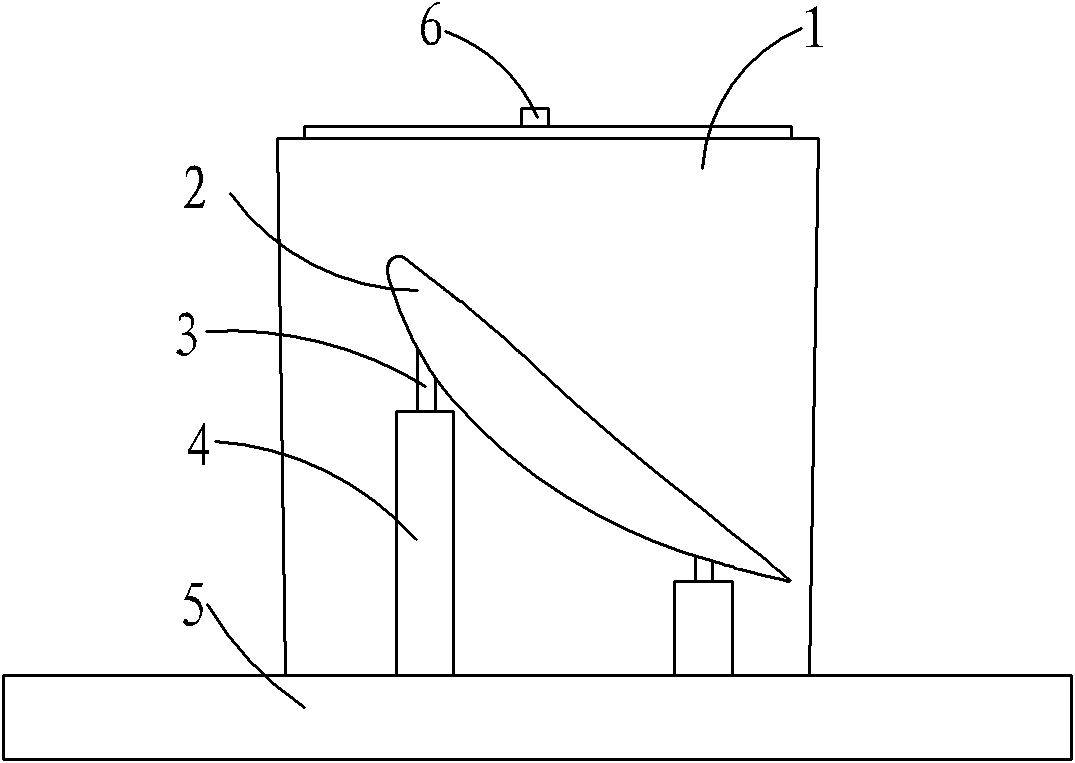
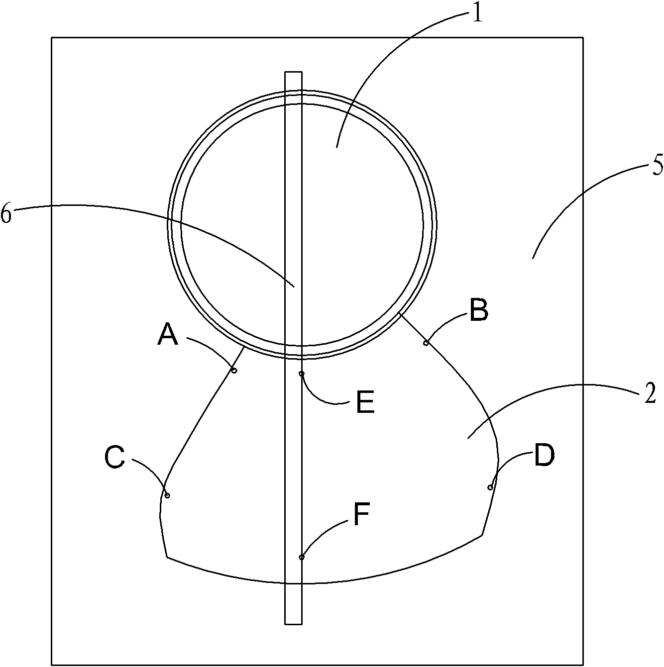
[0017] Please also see figure 1 with figure 2 As shown, the positioning process of the runner blade of the axial-flow fixed-pitch turbine includes the following steps:

[0018] Step 1: Carve out the alignment points E and F of the blade rotation centerline on the front of the blade 2. The alignment points E and F are the vertical projections of the rotation centerline of the blade 2 on the front of the blade 2 according to the placement angle specified in the design drawing;

[0019] Step 2: After milling the back of the blade 2, spot-weld four process positioning round bars 3, and mill out positioning planes of different heights on the end faces of the round bars;

[0020] Step 3: The hub 1 is placed on the assembly platform 5, and four bases 4 of appropriate sizes are distributed according to the positions of the hub 1 and the blade 2 where the round steel 3 is located;

[0021] Step 4: Place the blade 2 on the base 4 for profile positioning;

[0022] Step 5: Place a squ...


PUM


Abstract

The invention relates to a positioning technology for a runner blade of a propeller turbine, wherein, a blade rotating center line alignment point is carved on the front side of the blade; four technical positioning round steel bars are formed on the back side of the blade through spot welding after milling; positioning plane surfaces with unequal heights are milled on the end surfaces of the round steel bars; a hub is put on an assembling platform; four bases in corresponding sizes are distributed according to the positions that are positioned by the hub and the three positioning round steel bars of the blade; the moulding surface positioning can be achieved by putting the blade on the bases; in addition, a straight edge aligned with a center line is arranged on the upper plane surface of the hub, and the straight edge is aligned through a plumbing method, so that the alignment point of the blade is positioned on the center line. The positioning technology has the advantages of low cost, simple operation, low labor intensity and high assembling efficiency.

Description

【Technical field】 [0001] The invention belongs to the technical field of water turbine manufacturing, and in particular relates to a positioning process for runner blades of an axial-flow fixed-pitch water turbine. 【Background technique】 [0002] At present, most domestic water turbine factories use positioning pin holes on the center line of blade rotation for positioning the runner blades of axial-flow fixed-pitch turbines. Connect with the hub, then place the combination template on the blade profile, and correct the placement angle of the blade and the correct positioning of the blade profile according to the reference plane of the blade composite template. [0003] This positioning method has the following disadvantages: 1. It is difficult to locate and clamp when the positioning datum (rotation center hole) of the blade is drilled and reamed, because the positioning surface of the blade is an irregular curved surface; Design tooling (blade combination model) for align...

Claims


Application Information

Patent Timeline
Patent Type & Authority Applications(China)
IPC IPC(8): B25B11/00
Inventor 陈玉宇
Owner FUJIAN NANDIAN
Learn More