Needle bar driving mechanism of rotary shuttle loom for quilting and embroidering

A driving mechanism and a technology of a rotary hook machine, which are used in the rotary hook machine of quilting and embroidery, and the field of quilting, can solve the problems of inability to flexibly configure the spacing of quilting needles, difficult to meet the needs of the market, and inability to lock a single needle, so as to improve the operation. efficiency and operability, stable and reliable quality control, and the effect of structural optimization and adjustment

Active Publication Date: 2013-03-06
江西艺博达机械有限公司
View PDF0 Cites 0 Cited by
  • Summary
  • Abstract
  • Description
  • Claims
  • Application Information

AI Technical Summary

Problems solved by technology

[0002] Traditional quilting and quilting embroidery rotary hook machines, due to structural defects, the sewing needle spacing is generally 4 inches or more, which is difficult to meet the needs of the market
Subsequently, quilting embroidery mechanisms with small needle spacing (such as 2 inches) appeared, but in order to meet the structural design, a driver was used to drive two or more needle bars to move. This structure is used in actual production applications. There is a defect that a single needle cannot be locked. To lock, only all the needle bars of the same driver can be locked at the same time, which brings a lot of inconvenience to production.
For example: 1) When the thread on a needle breaks and needs mending embroidery, the associated needles must also follow the mending embroidery, resulting in overlapping sewing stitches; 2) The needle spacing of quilting and quilting embroidery cannot be flexibly configured

Method used


Image

  • Needle bar driving mechanism of rotary shuttle loom for quilting and embroidering
  • Needle bar driving mechanism of rotary shuttle loom for quilting and embroidering
  • Needle bar driving mechanism of rotary shuttle loom for quilting and embroidering

Examples


Embodiment Construction

[0017] The present invention is further described below in conjunction with accompanying drawing:

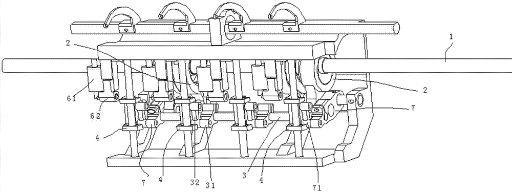
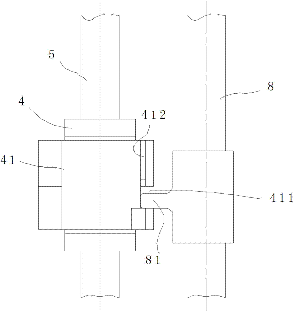
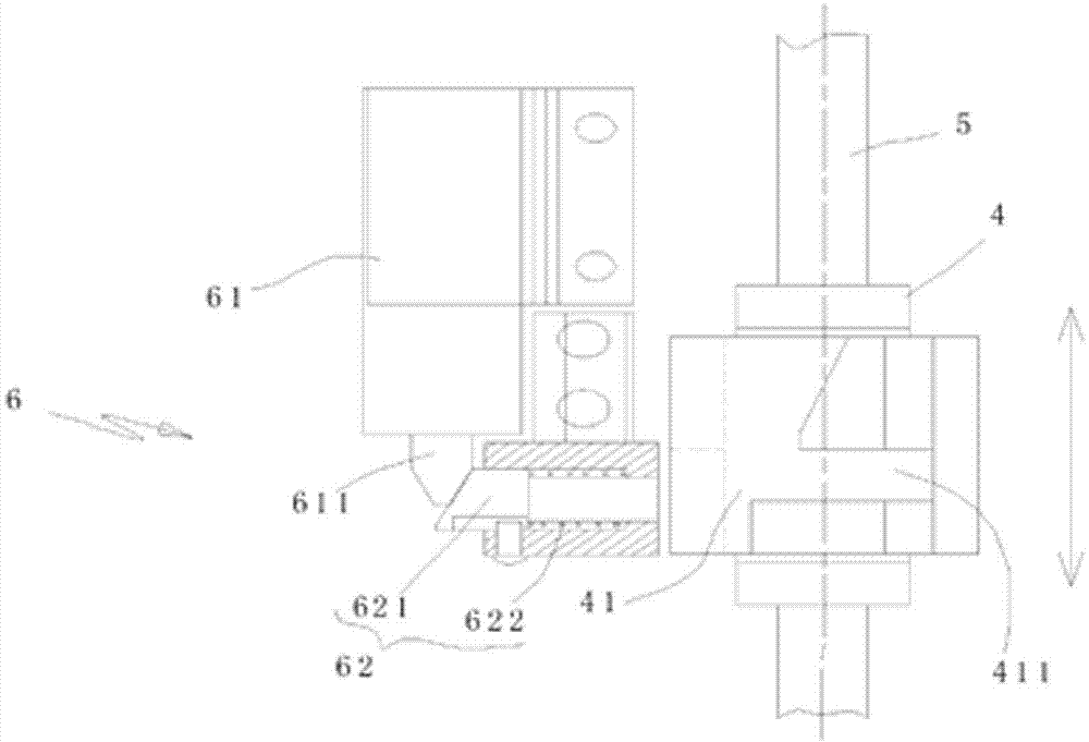
[0018] refer to Figure 1~4 As shown, it is a schematic diagram of a preferred embodiment of the present invention. The present invention relates to a needle bar driving mechanism of a rotary hook machine used for quilting and quilting embroidery, including a driving shaft 1, which is driven and connected by a cam 2. Axis 3 and connecting shaft 3 are linked with two or more drivers 4 that can move up and down. The drivers 4 are installed on a vertical rod 5, and each driver 4 corresponds to a needle bar; the driver 4 is provided with movable Block 41, the movable block 41 is provided with a card slot 411 that can lock the adapter part of the needle bar and drive the needle bar to move up and down; it also includes an unlocking mechanism 6 that can drive the card slot 411 to separate from the needle bar. Unlocking mechanism 6 comprises the electromagnet end lock device 61 of ver...


PUM


Abstract

The invention relates to the technical field of production machinery for quilting and embroidering, in particular to a rotary shuttle loom for quilting and embroidering. A needle bar driving mechanism of the rotary shuttle loom comprises a driving shaft, wherein the driving shaft drives a connecting shaft via cams; the connecting shaft is linked with two or more drivers which can move up and down; the drivers are installed on an upright bar; each driver corresponds to a needle bar; the drivers are provided with moving blocks which can move eccentrically; and the moving blocks are provided with clamp slots which can clamp the adaptation parts of the needle bars and drive the needle bars to move up and down. The needle bar driving mechanism also comprises an unlocking mechanism which can drive the clamp slots to be separated from the needle bars, wherein the unlocking mechanism comprises an electromagnet locking head device which is installed uprightly and a transverse propelling device. The needle bar driving mechanism has the following advantages: after the cams are output, the drivers are synchronously driven by the connecting shaft and three-hole connecting bars to move up and down, so the structure is optimized and adjusted and the spatial body is small; the unlocking mechanism has one-to-one relationship with the drivers, so the single needle locking function can be realized in the small needle gauge embroidering process and the production requirement is met; and the needle bar driving mechanism has simple, scientific and reasonable structure.

Description

technical field [0001] The invention relates to the technical field of production machinery for quilting and quilting embroidery, in particular to a hook for quilting and quilting embroidery. Background technique [0002] Traditional quilting and quilting embroidery rotary hook machines, due to structural defects, generally have a needle pitch of 4 inches or more, which is difficult to meet the needs of the market. Subsequently, quilting embroidery mechanisms with small needle spacing (such as 2 inches) appeared, but in order to meet the structural design, a driver was used to drive two or more needle bars to move. This structure is used in actual production applications. There is the defect of not being able to lock a single needle. To lock, all the needle bars of the same driver can only be locked at the same time, which brings a lot of inconvenience to production. For example: 1) When the thread on one needle breaks and needs mending embroidery, the associated needles m...

Claims


Application Information

Patent Timeline
Patent Type & Authority Patents(China)
IPC IPC(8): D05B55/16D05C11/06
Inventor 徐太阳
Owner 江西艺博达机械有限公司
Why Eureka
Try Eureka