Fuel injection device
A fuel injection device, fuel technology, applied in the direction of fuel injection device, charging system, engine components, etc., can solve the problems of fuel pressure drop, fuel injection interruption, leakage, etc.
- Summary
- Abstract
- Description
- Claims
- Application Information
AI Technical Summary
Problems solved by technology
Method used
Image
Examples
Embodiment 1
[0032] [Structure of Embodiment 1]
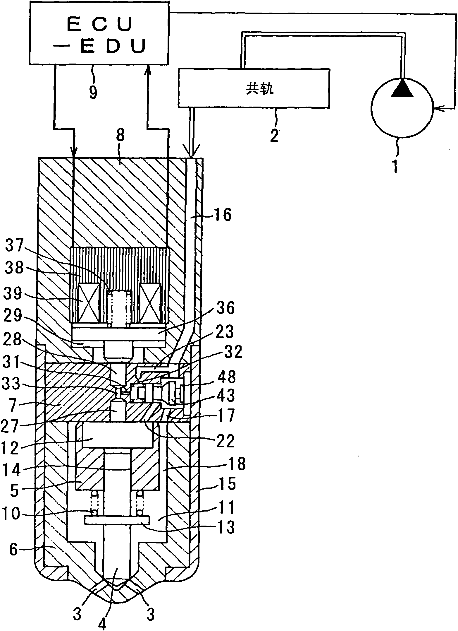
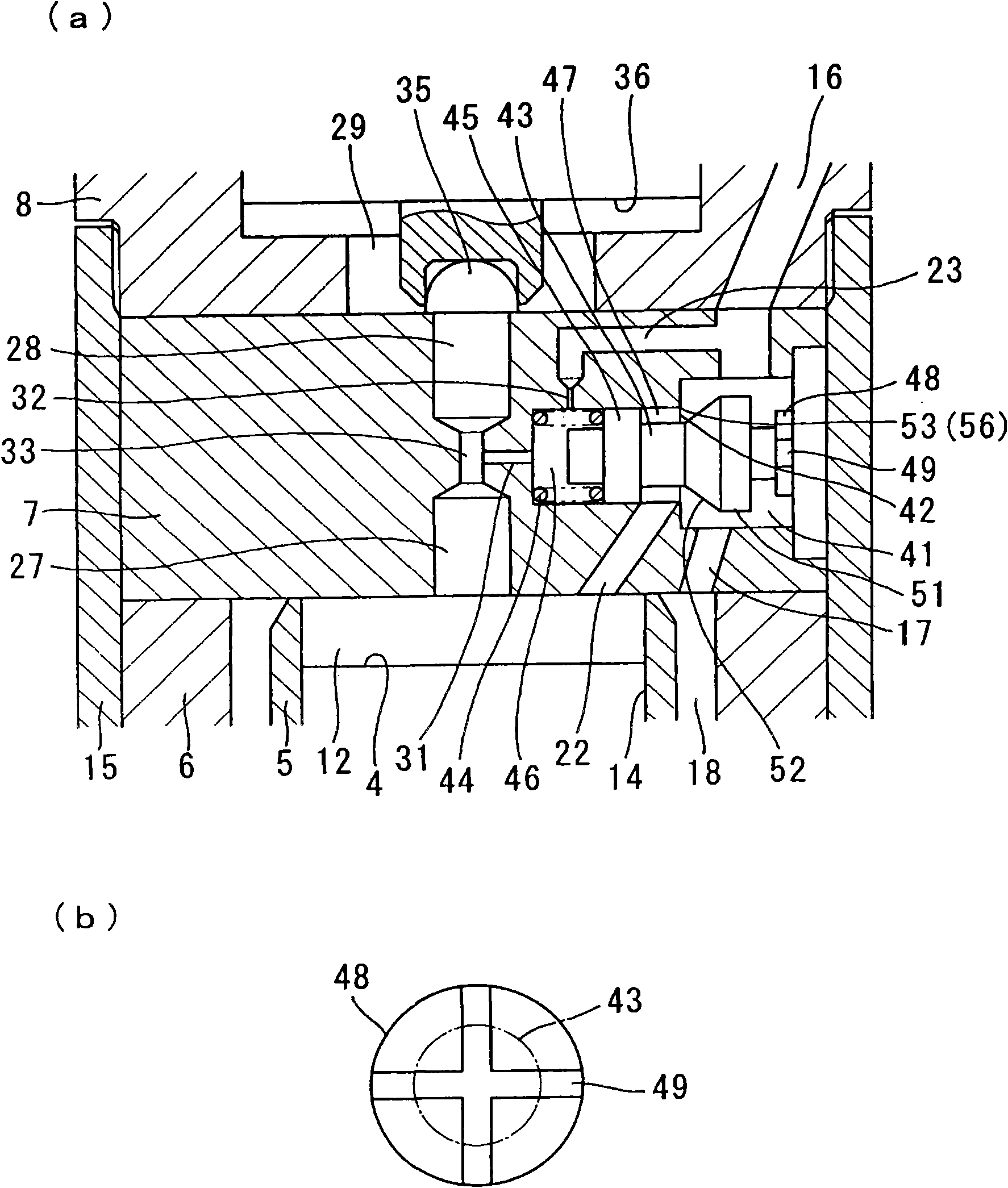
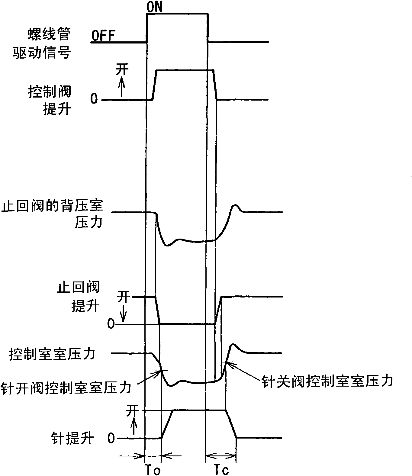
[0033] Figure 1 to Figure 3 Shown is embodiment 1 of the present invention, figure 1 is a diagram showing a common rail fuel injection device, figure 2 (a) is a figure showing the periphery of the orifice plate of the injector, figure 2 (b) is a figure which shows the cross groove formed in the stopper, image 3 It is a timing chart showing the working state of the injector.
[0034] The fuel supply device for the internal combustion engine of the present embodiment is assembled in the engine room of a vehicle such as an automobile, and is composed of a common rail type fuel injection system (accumulation type fuel injection system). This common rail type fuel injection system is used As a fuel injection system for internal combustion engines (engines) such as diesel engines with multiple cylinders.
[0035] The common rail fuel injection system includes: a transfer pump 1 that pressurizes the sucked fuel; a common rail 2 that intr...
Embodiment 2
[0177] Figure 4 (a) and Figure 4 (b) represents embodiment 2 of the present invention, Figure 4 (a) is a figure showing the periphery of the orifice plate of the injector, Figure 4 (b) is a figure which shows the cross groove formed in the stopper. here, Figure 4 (a) shows the status of the electromagnetic control valve closed, the check valve opened, and the needle 4 closed.
[0178] The check valve of this embodiment has: an orifice plate (valve body) 7 with a hollow portion (plug hole, pressure chamber 41) formed inside; a cylindrical valve plug (slide valve) 43 for switching on and off from the fuel supply flow The channel 16 introduces a gap (valve hole) 42 through which high-pressure fuel is introduced into the control chamber 12 via the fuel introduction channel 22;
[0179] The valve plug hole accommodates the valve plug 43 for opening and closing the gap 42 of the check valve, so that the valve plug 43 can move back and forth along the axial direction (movin...
Embodiment 3
[0189] Figure 5 Shown is Example 3 of the present invention, which is a view showing the peripheral portion of the orifice plate of the injector. here, Figure 5 It shows the state that the electromagnetic control valve is opened, the check valve is closed, and the needle 4 is opened, and the fuel is injected from the injection hole 3.
[0190] The check valve of this embodiment has: a valve body in which a hollow portion (plug hole, pressure chamber 41) is formed; The passage 22 introduces a gap (valve hole) 42 through which high-pressure fuel is introduced into the control chamber 12; and a spring 44 applies a biasing force to the valve plug 43 in the valve opening direction of the valve hole.
[0191] The valve body is composed of an orifice plate 7, an injector body 8, and the like.
[0192] The hollow portion is constituted by a recess (plug hole) opened on the second contact surface of the orifice plate 7 , a recess (pressure chamber 41 ) opened on the second connect...
PUM
 Abstract
Description
Claims
Application Information
 - R&D
- Intellectual Property
- Life Sciences
- Materials
- Tech Scout
- Unparalleled Data Quality
- Higher Quality Content
- 60% Fewer Hallucinations
Browse by: Latest US Patents, China's latest patents, Technical Efficacy Thesaurus, Application Domain, Technology Topic, Popular Technical Reports.
© 2025 PatSnap. All rights reserved.Legal|Privacy policy|Modern Slavery Act Transparency Statement|Sitemap|About US| Contact US: help@patsnap.com


