Fuel injection device

A fuel injection device, fuel technology, applied in the direction of fuel injection device, charging system, engine components, etc., can solve the problems of fuel pressure drop, fuel injection interruption, leakage, etc.

Active Publication Date: 2013-01-16
DENSO CORP
View PDF4 Cites 0 Cited by
  • Summary
  • Abstract
  • Description
  • Claims
  • Application Information

AI Technical Summary

Problems solved by technology

[0011] However, in the case of the injector of prior art 2, when the valve 121 of the electromagnetic control valve is opened, the fuel in the control chamber 104 will flow out from the outlet orifice 119, causing the fuel pressure in the control chamber 104 to drop, And a lot of high-pressure fuel will be discharged from the inlet orifice 118 to the low-pressure side due to the suction effect generated by the fuel flow rate flowing through the fuel discharge flow path 116, the so-called spray effect (or injector effect).
[0012] In addition, the injection water hammer (pressure fluctuation) caused by the valve opening of the needle 102 is applied to the intermediate valve 108 from the fuel supply channels 111 to 113 and the fuel introduction channels 114 and 115, causing the intermediate valve 108 to open.
The opening of the intermediate valve 108 may cause high-pressure fuel to flow into the control chamber 104 during the fuel injection, causing the needle 102 to close the valve and causing fuel injection to be interrupted.
[0013] Moreover, since the middle valve 108 is in the shape of a flat plate, the contact with the seat surface of the orifice plate 106 (seating) is realized in a plane, therefore, when the needle 102 opens the valve, it is easy for the high-pressure fuel to flow from the fuel introduction flow path 115 to the control chamber. Leaks in 104 that could affect stable fuel injection

Method used


Image

  • Fuel injection device
  • Fuel injection device
  • Fuel injection device

Examples


Embodiment 1

[0032] [Configuration of Example 1]

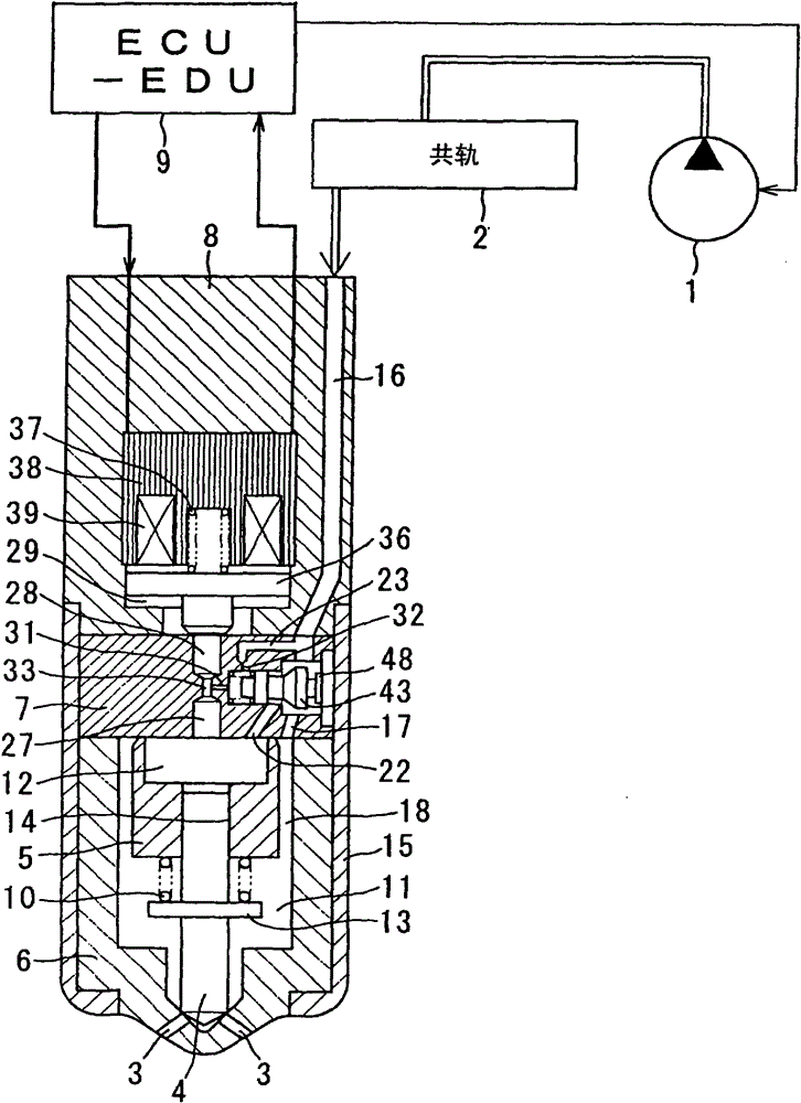
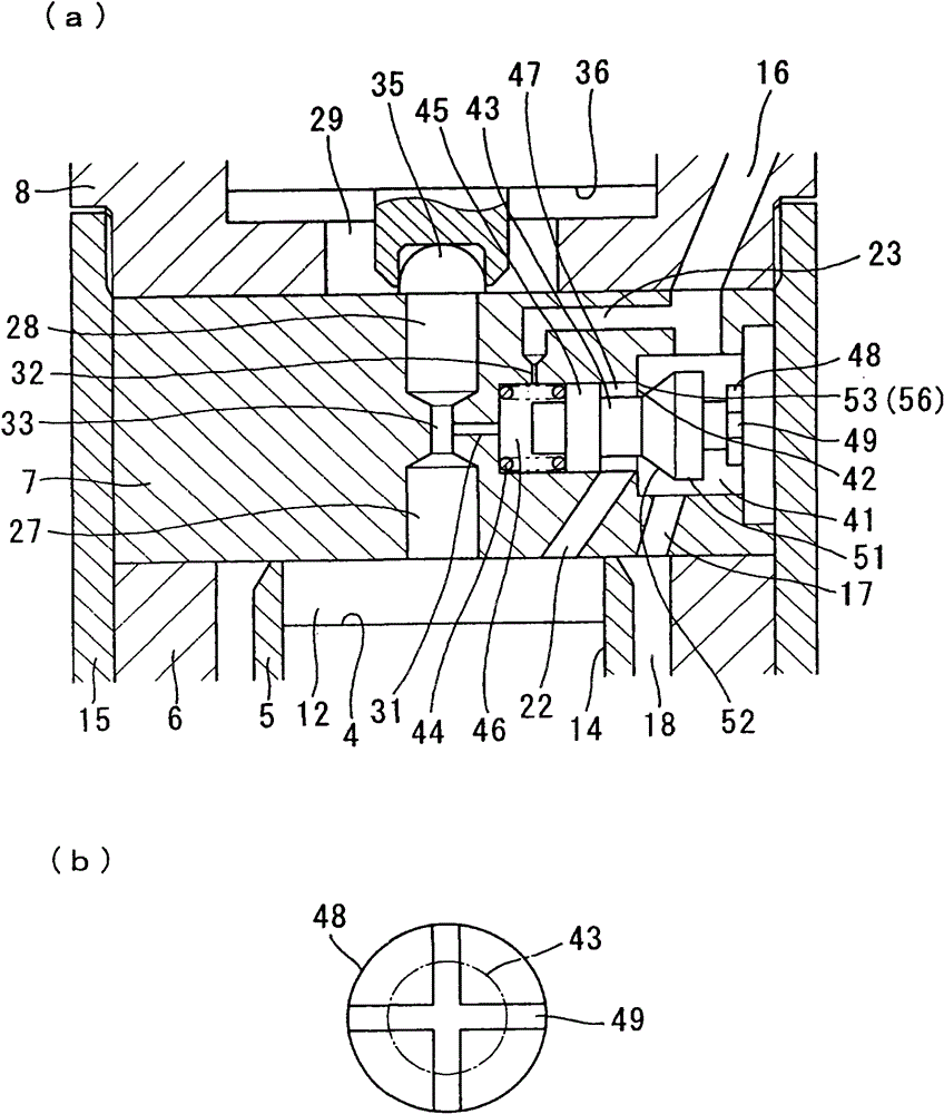
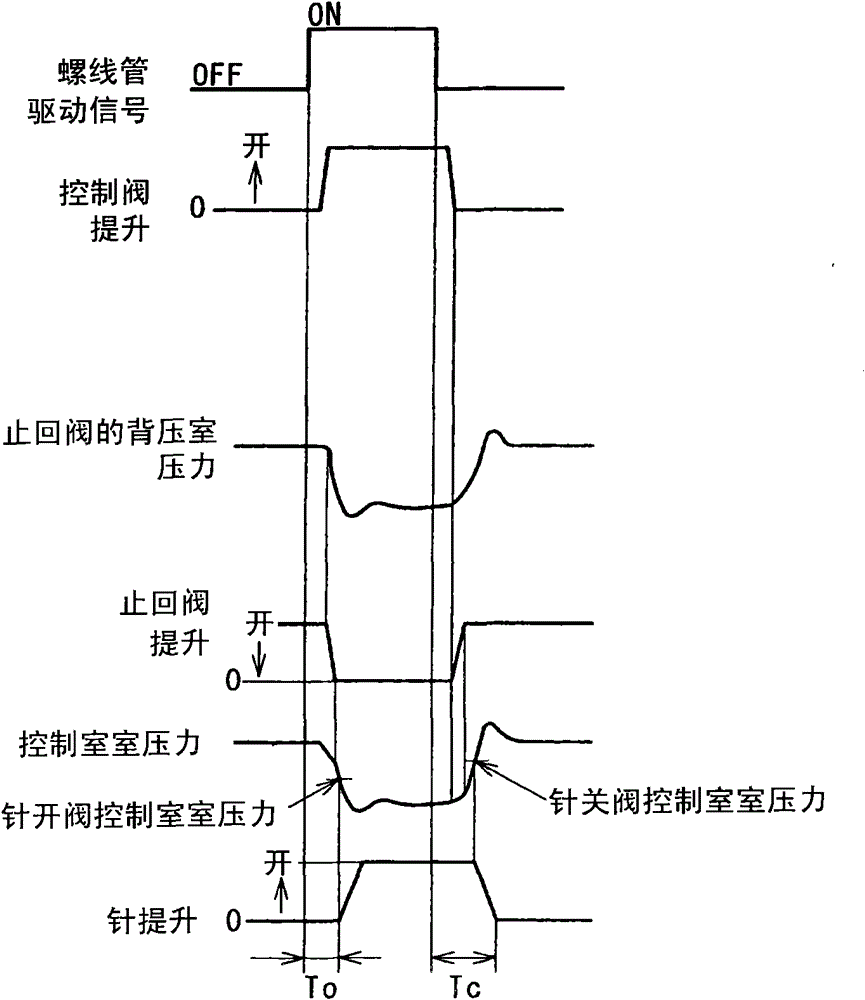
[0033] Figure 1 to Figure 3 What is shown is Embodiment 1 of the present invention, figure 1 is a diagram showing a common rail fuel injection device, figure 2 (a) is a diagram showing the periphery of the orifice plate of the injector, figure 2 (b) is a diagram showing a cross groove formed in the stopper, image 3 is a timing chart showing the operating state of the injector.

[0034] The fuel supply device for the internal combustion engine of the present embodiment is installed in an engine room of a vehicle such as an automobile, and is constituted by a common rail type fuel injection system (accumulator type fuel injection system), which is used for It is used as a fuel injection system for an internal combustion engine (engine) such as a diesel engine having a plurality of cylinders.

[0035] The common rail type fuel injection system includes: a transfer pump 1 for pressurizing the sucked fuel; a common rail 2 for introduc...

Embodiment 2

[0177] Figure 4 (a) and Figure 4 (b) represents Embodiment 2 of the present invention, Figure 4 (a) is a diagram showing the periphery of the orifice plate of the injector, Figure 4 (b) is a figure which shows the cross groove formed in the stopper. here, Figure 4 (a) shows the state in which the solenoid control valve is closed, the check valve is open, and the needle 4 is closed.

[0178] The check valve of the present embodiment has an orifice plate (valve body) 7 in which a hollow portion (plug hole, pressure chamber 41 ) is formed, and a cylindrical valve plug (spool valve) 43 for opening and closing the flow from the fuel supply. The passage 16 introduces the clearance (valve hole) 42 of the high pressure fuel to the control chamber 12 via the fuel introduction passage 22;

[0179] The spool hole accommodates a spool 43 for opening and closing the gap 42 of the check valve, so that the spool 43 can move back and forth in the axial direction (moving direction) o...

Embodiment 3

[0189] Figure 5 It shows Example 3 of this invention, and it is a figure which shows the peripheral part of the orifice plate of an injector. here, Figure 5 It shows the state in which the electromagnetic control valve is opened, the check valve is closed, and the needle 4 is opened, and the fuel is injected from the injection hole 3 .

[0190] The check valve of the present embodiment has a valve body with a hollow portion (plug hole, pressure chamber 41 ) formed therein, and a cylindrical valve plug (spool valve) 43 for opening and closing the flow of fuel from the fuel supply flow path 16 through the fuel introduction. The passage 22 introduces a gap (valve hole) 42 for high-pressure fuel into the control chamber 12; and a spring 44, which imparts an urging force to the valve plug 43 in the valve opening direction.

[0191] The valve body is composed of the orifice plate 7, the injector body 8, and the like.

[0192] The hollow portion is constituted by a concave porti...


PUM


Abstract

A fuel injection device is provided, wherein a fuel introducing flow path (22) for introducing high-pressure fuel into a control room (12) from a fuel supplying flow path (16), and a check valve for controlling the opening and the closing of a clearance (42) are formed inside an orifice plate (7). Therefore, the time (valve-opening response time) from the opening of a solenoid-controlled valve tothe opening of a needle (4) is shortened. In addition, the time (valve-closing response time) from the closing of the solenoid-controlled valve to the closing of the needle (4) is shortened. The closing of the needle (4) is accelerated, and the valve-closing responsiveness is improved. Additionally, in an injection period that the solenoid-controlled valve is opened, the check valve is closed andthe needle (4) is opened, the check valve closes the fuel introducing flow path (22) with a larger flow path section area, so abnormal injection actions such as the closing of the needle (4) can be prevented during the fuel injection into a combustion chamber of a cylinder of an engine.

Description

technical field [0001] The present invention relates to a fuel injection device for injecting fuel into a combustion chamber of an internal combustion engine, and more particularly, to a fuel injection device that uses at least two first and second control valves to control the fuel pressure in the control chamber, thereby improving needle pressure. A fuel injection device (injector) with valve opening responsiveness and needle valve closing responsiveness. Background technique [0002] In the past, as Figure 10 and Figure 11 As shown, a known fuel injection device (injector of the prior art 1) is provided with the following members (for example, refer to Japanese Patent Laid-Open No. 09-032681): a needle 102 for opening and closing a combustion chamber of an internal combustion engine (engine) The nozzle hole 101 for injecting fuel; the nozzle chamber 103 , the fuel pressure inside the nozzle chamber 103 , which applies the oil pressure in the valve opening direction of ...

Claims


Application Information

Patent Timeline
Patent Type & Authority Patents(China)
IPC IPC(8): F02M47/02F02M61/10F02M61/20
Inventor 竹内久晴加藤正明足立尚史
Owner DENSO CORP
Why Eureka
Try Eureka