Solenoid operated fuel injection valve

A fuel injection valve, electromagnetic technology, applied in the direction of fuel injection devices, charging systems, engine components, etc., can solve the problems of insufficient valve opening response, large side clearance, and insufficient magnetic flux transmission efficiency, etc., to achieve improved Effects of valve opening responsiveness, improvement of attraction force, and improvement of transmission efficiency

Active Publication Date: 2010-04-21
HITACHI ASTEMO LTD
View PDF5 Cites 0 Cited by
  • Summary
  • Abstract
  • Description
  • Claims
  • Application Information

AI Technical Summary

Problems solved by technology

[0004] However, in the above-mentioned conventional electromagnetic fuel injection valve, the movable iron core is provided with an annular sliding contact convex portion slidingly contacting the inner surface of the non-magnetic cylinder, and the magnetic cylinder and the movable iron The side gap between the cores is relatively large, resulting in insufficient flux transmission efficiency and insufficient valve opening response.

Method used


Image

  • Solenoid operated fuel injection valve
  • Solenoid operated fuel injection valve
  • Solenoid operated fuel injection valve

Examples


Embodiment 1

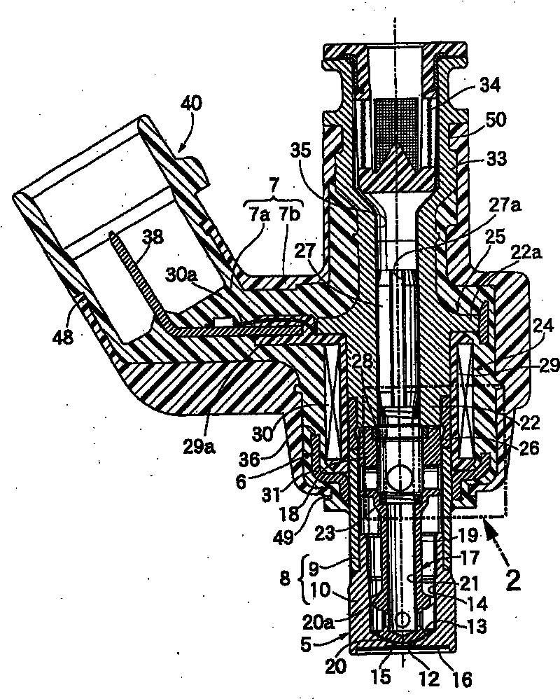
[0019] refer to figure 1 and figure 2 An embodiment of the present invention is described, first in figure 1 Among them, an electromagnetic fuel injection valve for injecting fuel to an unillustrated engine includes: a valve part 5 configured to house a valve body 20 in a valve housing 8 having a valve seat 13 at its front end The above-mentioned valve body 20 is applied with elastic force in the direction of falling on the above-mentioned valve seat 13; the electromagnet part 6 is configured to accommodate a coil assembly 24 in an electromagnet housing 25 connected to the above-mentioned valve housing 8, This coil assembly 24 can generate the electromagnetic force that drives the above-mentioned valve body 20 to the side away from the above-mentioned valve seat 13; The assembly 24 and the electromagnet housing 25 , wherein the connector 40 faces the connecting terminals 38 . . . connected to the coil 30 of the coil assembly 24 .

[0020] The valve housing 8 is composed of...


PUM


Abstract

A solenoid operated fuel injection valve, wherein a valve element is stored in a valve housing having a magnetic cylindrical body, the front end of a non-magnetic cylindrical body surrounding a part of a movable core continuously connected coaxially with the valve element is coaxially connected to the rear end of the magnetic cylindrical body, and a fixed core is fixedly fitted to the rear part ofthe non-magnetic cylindrical body. The movable core (18) comprises a sliding tube part (18a) having an outer peripheral surface in slidable contact with the rear inner peripheral surface of the magnetic cylindrical body, a rear opposed tube part (18b) continuously connected to the rear end of the sliding tube part (18a) coaxially and integrally with each other and having an outer periphery opposedto the inner periphery of the magnetic cylindrical body (9), and a front opposed tube part (18c) having an outer periphery opposed to the inner periphery of the magnetic cylindrical body (9) and cont inuously connected to the front end of the sliding tube part (18a) coaxially and integrally with each other. Where the diameter of the rear opposed tube part (18b) is D1, the diameter of the front opposed tube part (18c) is D2, and the diameter of the sliding tube part (18a) is D3, they are set to the relation of D1 < D2 < D3. Thus, the responsiveness of the fuel injection valve for valve openingcan be increased by increasing a magnetic flux delivery efficiency between the movable core and the magnetic cylindrical body.

Description

technical field [0001] The present invention relates to an electromagnetic fuel injection valve. The electromagnetic fuel injection valve includes: a valve housing composed of a valve seat member having a valve seat, and a magnetic cylinder whose front end is coaxially connected to the valve seat member. The valve assembly is composed of a valve body and a movable iron core, and elastic force is applied to the side where the valve body is placed on the valve seat, and the valve body can be placed on the valve seat and accommodated in the valve housing , the above-mentioned movable iron core is coaxially connected with the above-mentioned valve body, and the rear end surface is used as the movable side attracting action surface; the non-magnetic cylinder, the front end of which is coaxially combined with the rear end of the above-mentioned magnetic cylinder, and The non-magnetic cylindrical body surrounds a part of the above-mentioned movable iron core; and a fixed iron core ha...

Claims


Application Information

Patent Timeline
Patent Type & Authority Patents(China)
IPC IPC(8): F02M51/06F02M61/12
CPCF02M61/12F02M61/166F02M51/0682
Inventor 赤羽根明
Owner HITACHI ASTEMO LTD
Why Eureka
Try Eureka