
Control device for an internal combustion engine

a control device and internal combustion engine technology, applied in the direction of electric control, combustion engines, machines/engines, etc., can solve the problems of increasing the consumption of electricity by the actuator, generating a significant counter electromotive force in the actuator, and taking a longer time to eliminate the significant counter electromotive, so as to achieve the valve opening responsiveness required for the waste gate valve further increase, the effect of high acceleration performan

Active Publication Date: 2019-09-17
HONDA MOTOR CO LTD
View PDF5 Cites 0 Cited by
  • Summary
  • Abstract
  • Description
  • Claims
  • Application Information

AI Technical Summary

Benefits of technology

This approach effectively prevents waste gate valve vibration, reduces electricity consumption, and enhances valve opening responsiveness, allowing for prompt adjustment of supercharging pressure to prevent overshooting.

Problems solved by technology

However, while the internal combustion engine is running as described above, when the electrification amount of the actuator is increased in order to maintain the waste gate valve in a fully closed state, there is a possibility that not only will consumption of electricity by the actuator increase but also a significant counter electromotive force will be generated in the actuator.
Therefore, when the waste gate valve is opened from the fully closed state, it takes a longer time to eliminate the significant counter electromotive force, and particularly, the operation of starting valve-opening is likely to be delayed.
As a result, the increased supercharging pressure cannot be promptly lowered, and thus, for example, there is a possibility that overshooting of the supercharging pressure exceeding an upper limit value will occur.

Method used


Image

  • Control device for an internal combustion engine
  • Control device for an internal combustion engine
  • Control device for an internal combustion engine

Examples


Embodiment Construction

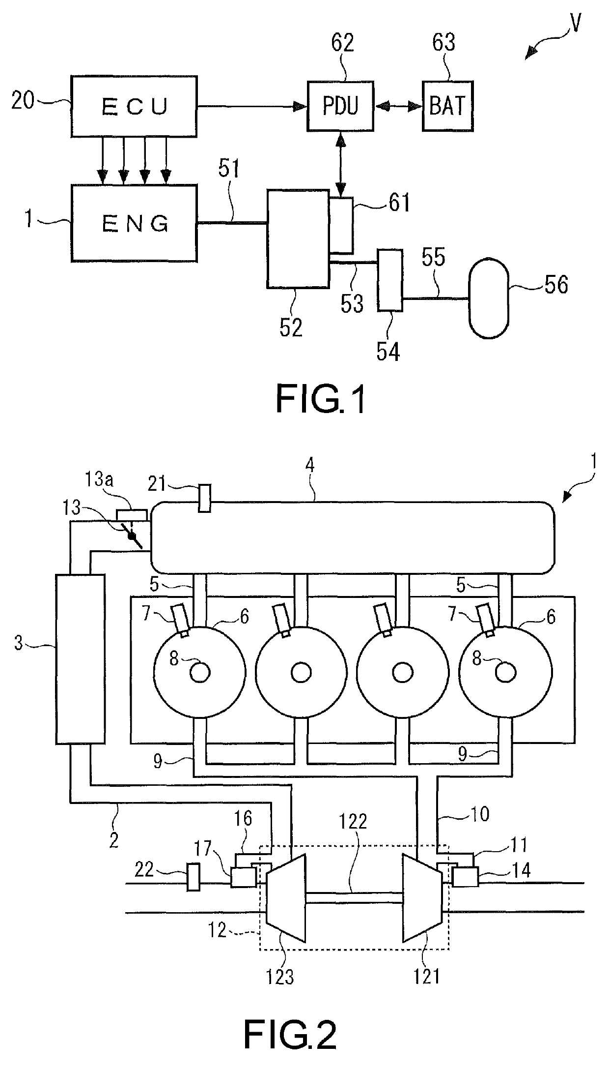
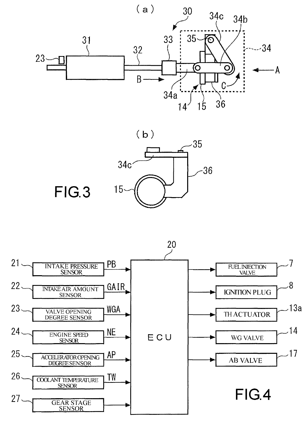
[0027]Hereinafter, with reference to the drawings, a preferable embodiment of the present invention will be described in detail. As illustrated in FIG. 1, a vehicle V is a hybrid vehicle including an internal combustion engine (hereinafter, will be referred to as “engine”, and it is referred to as “ENG” in FIG. 1) 1 which serves as a driving source, and an electric motor (hereinafter, will be referred to as “motor”) 61 which functions as a driving source and a generator. The vehicle V includes a transmission 52 which shifts a driving force of the engine 1 and / or the motor 61.

[0028]The motor 61 is connected to a power drive unit (hereinafter, will be referred to as “PDU”) 62, and the PDU 62 is connected to a high-voltage battery 63. When the motor 61 is driven with positive driving torque, that is, when the motor 61 is driven with electricity output from the high-voltage battery 63, the electricity output from the high-voltage battery 63 is supplied to the motor 61 via the PDU 62. In...


PUM


Abstract

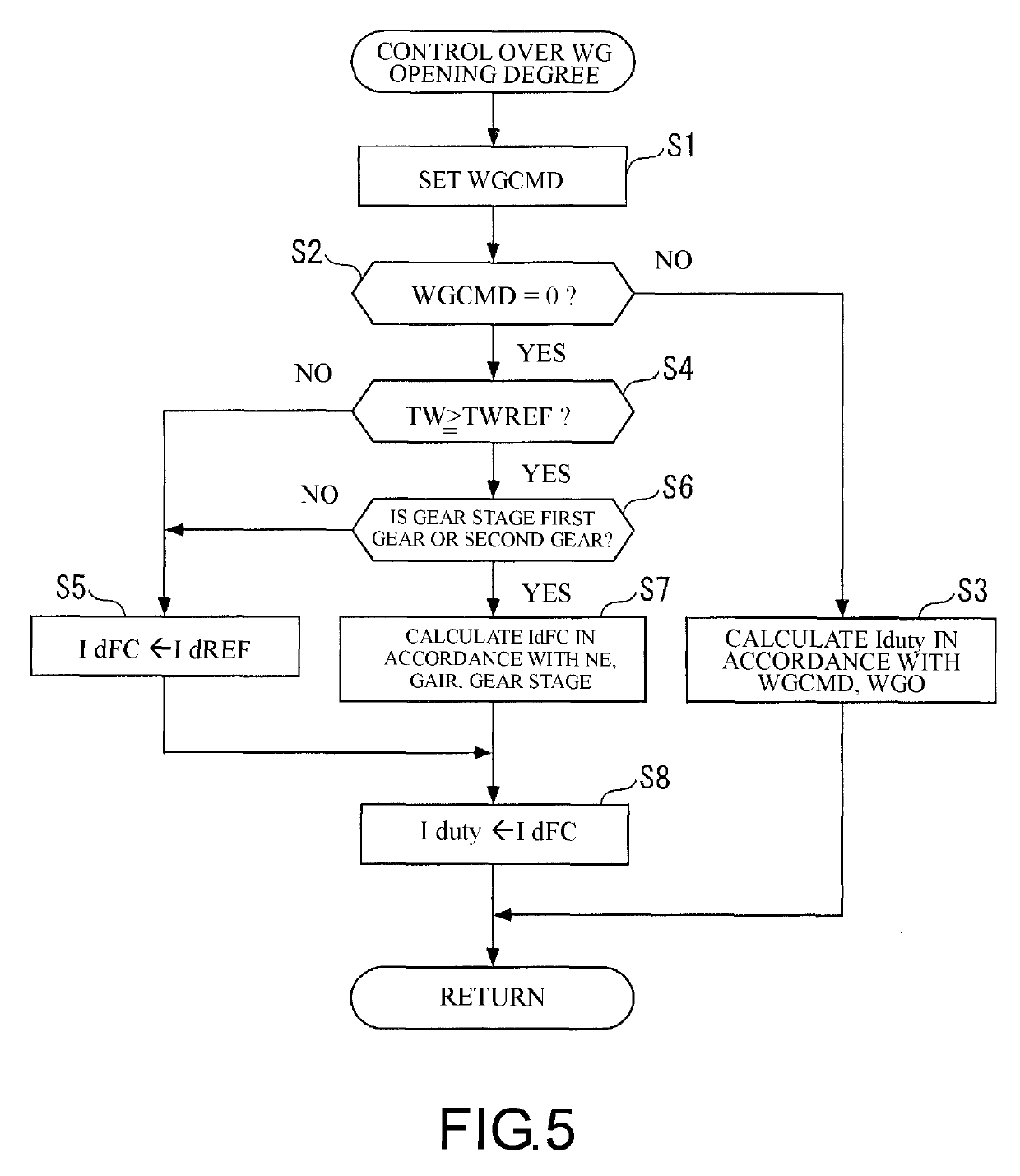
A control device for an internal combustion engine, in which vibration of a waste gate valve in a fully closed state and disadvantages caused due to the vibration thereof while the internal combustion engine is running are prevented, and valve opening responsiveness of the waste gate valve can be improved. In a control device for an internal combustion engine, an opening degree of a waste gate valve 14 is controlled by controlling an electrification duty ratio Iduty of the motor 31. In addition, a fully closed period duty ratio IdFC, which is an electrification duty ratio Iduty when the opening degree of the waste gate valve 14 is controlled to be in a fully closed state, is controlled such that the fully closed period duty ratio IdFC becomes smaller when a detected engine speed NE of an internal combustion engine (1) increases (Step 7 in FIG. 5, FIG. 7).

Description

CROSS-REFERENCE TO RELATED APPLICATION[0001]This application claims the priority benefit of Japan application serial no. 2016-240699, filed on Dec. 12, 2016. The entirety of the above-mentioned patent application is hereby incorporated by reference herein and made a part of this specification.BACKGROUND OF THE INVENTION[0002]Field of the Invention[0003]The present invention relates to a control device for an internal combustion engine having a waste gate valve which is provided in a bypass passage bypassing a turbine of a supercharger supercharging intake air and regulates supercharging pressure generated by the supercharger.[0004]Description of Related Art[0005]Patent Document 1 discloses a control device for an internal combustion engine as an example of known control devices in the related art. The internal combustion engine is mounted in a vehicle as a driving source and includes a waste gate valve including an electric actuator. In this vehicle, idling stop control for automati...

Claims


Application Information

Patent Timeline
Patent Type & Authority Patents(United States)
IPC IPC(8): F02B37/18F02D41/00F02D23/00F02D41/02F02D41/20
CPCF02B37/183F02D41/0007F02D2041/2027Y02T10/144F02D2200/101F02D23/00F02D41/0225F02B37/186Y02T10/12
Inventor KURAUCHI, ATSUSHI
Owner HONDA MOTOR CO LTD
Learn More