LED shadowless lamp

A technology of LED shadowless lamps and shadowless lamps, applied in lighting devices, light sources, fixed lighting devices, etc., can solve the problems of dark spots, glare, and low light efficiency of the mask, and achieve the effects of uniform light, improved light efficiency, and high light efficiency

Inactive Publication Date: 2011-06-29
深圳辰泽科技有限公司
View PDF4 Cites 4 Cited by
  • Summary
  • Abstract
  • Description
  • Claims
  • Application Information

AI Technical Summary

Problems solved by technology

Multiple point light sources on the wiring board form a shadow area where the LED light cannot intersect, so that the LED light cannot be cross-mixed evenly, and glare will still occur
[0004] The above-mentioned LED light does not cro

Method used


Image

  • LED shadowless lamp
  • LED shadowless lamp
  • LED shadowless lamp

Examples


Example Embodiment

[0020] The technical solutions in the embodiments of the present invention will be clearly and completely described below in conjunction with the drawings in the embodiments of the present invention.

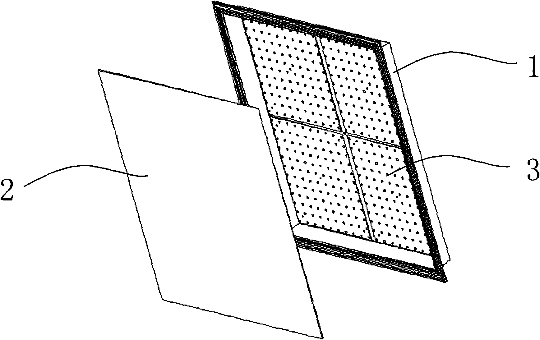
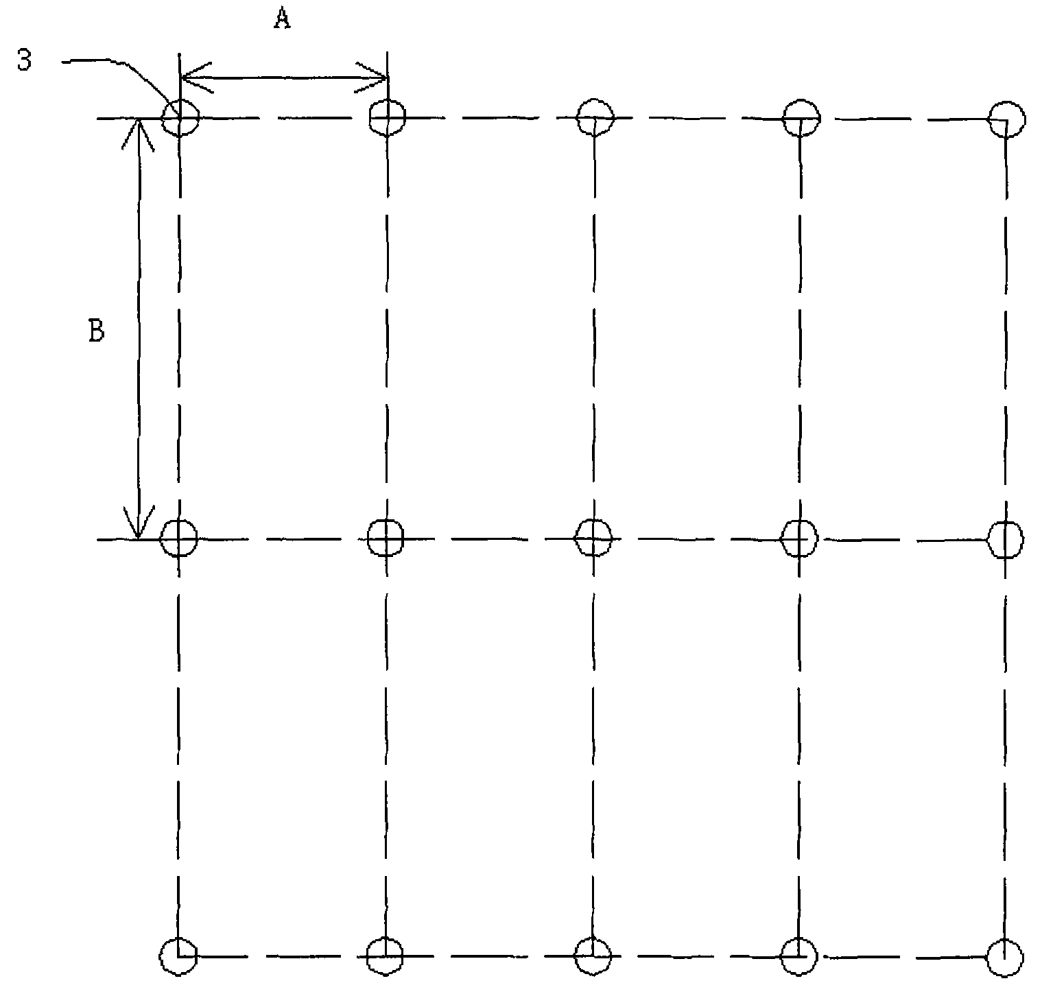
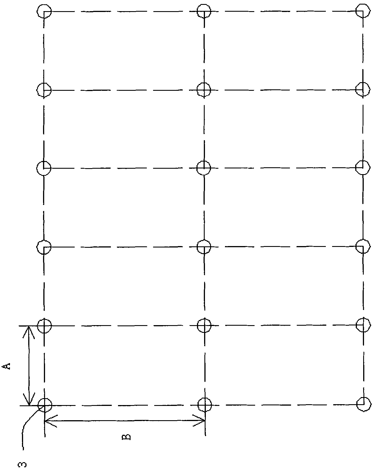
[0021] Such as figure 1 Shown: LED shadowless lamp, including lamp panel 1, diffuser plate 2 and LED light source 3. The opening of lamp panel 1 is closed by diffuser plate 2; LED light source 3 is arranged in a matrix at the bottom of lamp panel 1, such as figure 2 As shown, the matrix of LED light sources 3 is arranged in a square, such as image 3 As shown, the matrix of LED light sources 3 is arranged in a rectangular shape; the lateral distance between two laterally adjacent LED light sources 3 is A, and the longitudinal distance between two longitudinally adjacent LED light sources 3 is B.

[0022] Combine Figure 4 , Figure 5 As shown, the light emitted by two laterally adjacent LED light sources 3 form a cross, and the light emitted by two longitudinally adjacent LED light s...


PUM


Abstract

The invention relates to a light emitting diode (LED) shadowless lamp. The lamp comprises a lamp disc, a diffusion plate and LED light sources, wherein an opening of the lamp disc is sealed by the diffusion plate; and the diffusion plate 2 is positioned at a position which is one or two times the longitudinal distance of two adjacent LED light sources (3) away from the adjacent LED light sources (3), so that light rays emitted by the LED light sources are crossed and emitted, the adjacent LED light sources cannot form a shadow on the diffusion plate, and the lamp has the advantages that: the emitted light rays are uniform, LED light source particles cannot be seen during work, and a shadowless effect is achieved.

Description

technical field [0001] The invention relates to a lamp, in particular to an LED shadowless lamp. Background technique [0002] Existing LED (Light Emitting Diode, light-emitting diode) lamps and light sources are mostly point light sources, which are prone to dazzling glare. Watching for a long time will cause fatigue and even cause vision loss. Chinese invention patent CN201110498 discloses a lighting device, which specifically belongs to a lamp panel illuminated by LEDs, including a lamp panel shell and a lampshade. The grille is composed of parabolic reflectors arranged symmetrically up and down and left and right to form a grid. The reflectors in the grid are arranged between the reflectors and the reflectors to form an independent reflection chamber with a large surface and a small arc-shaped trapezoid. Each independent reflection chamber There are LED lights at the bottom. The patent only reveals how to maximize the efficiency of LEDs to save power consumption, and a...

Claims


Application Information

Patent Timeline
IPC IPC(8): F21S2/00F21V17/00F21V19/00F21Y101/02F21S8/00F21Y115/10
Inventor 徐彦波
Owner 深圳辰泽科技有限公司
Why Eureka
Try Eureka