Refrigeration dehumidifying device and control method thereof

A control method and control unit technology, which is applied in heating and ventilation control systems, heating methods, household heating, etc., can solve problems such as impacting the power grid, achieve improved safety, and avoid the effect of large currents impacting the power grid

Inactive Publication Date: 2011-06-29
广东力优环境系统股份有限公司
View PDF0 Cites 11 Cited by
  • Summary
  • Abstract
  • Description
  • Claims
  • Application Information

AI Technical Summary

Problems solved by technology

[0004] The technical problem to be solved by the present invention is to provide a refrigerated dehumidifier and a control method for the problem that

Method used


Image

  • Refrigeration dehumidifying device and control method thereof
  • Refrigeration dehumidifying device and control method thereof
  • Refrigeration dehumidifying device and control method thereof

Examples


Example Embodiment

[0023] The refrigerating and dehumidifying device and control method of the present invention turn on a plurality of high-power components sequentially, thereby avoiding a large current impact on the power grid caused by multiple high-power components being turned on at the same time, and greatly improving the safety of the equipment. The invention is mainly realized by the PLC program communicating with the upper computer.

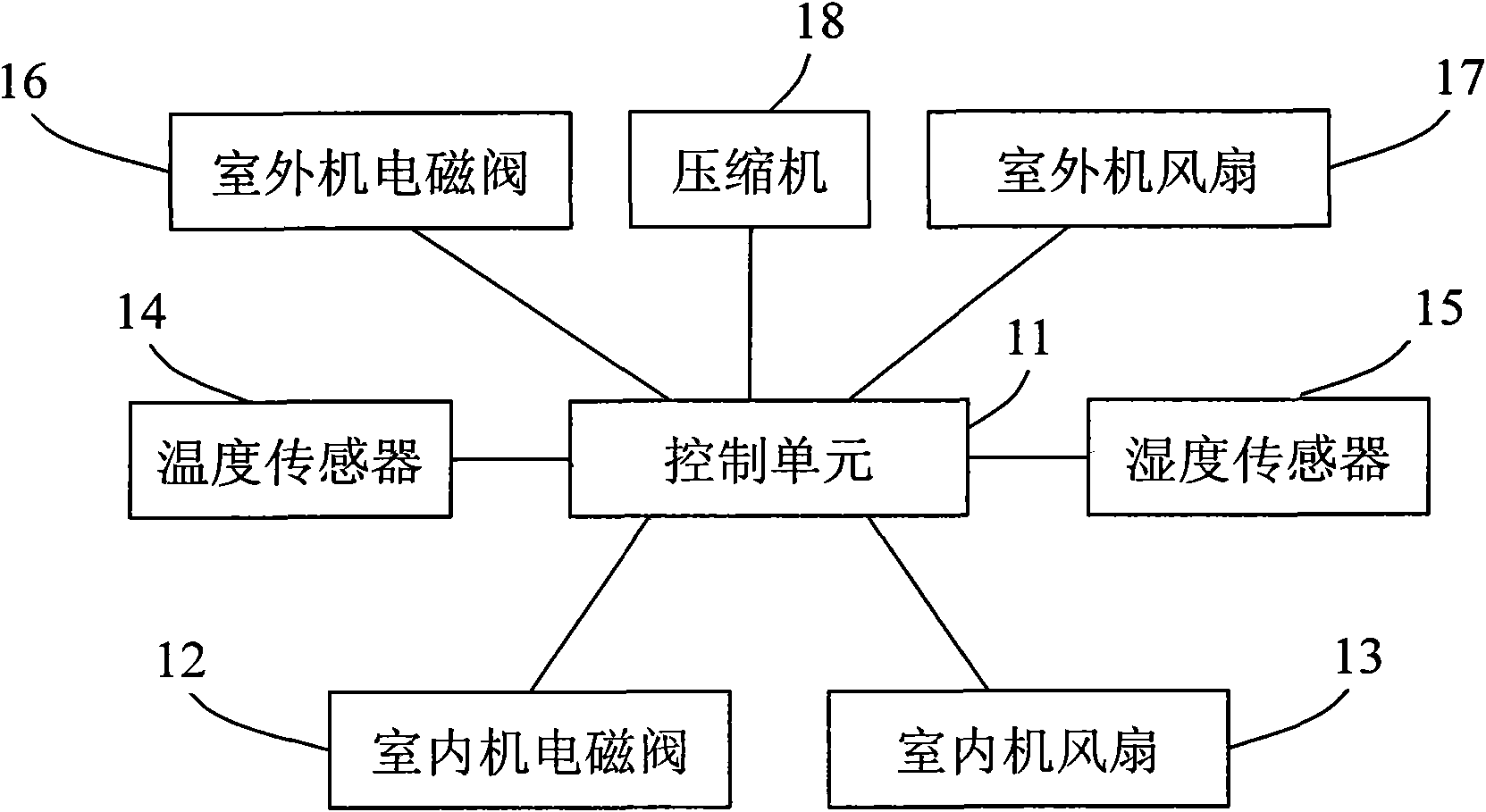
[0024] Such as figure 1 Shown is a schematic diagram of an embodiment of the freezing and dehumidifying device of the present invention. The device includes humidity sensor 15, temperature sensor 14, indoor unit fan 13, indoor unit solenoid valve 12 (used to control the indoor condenser), outdoor unit solenoid valve 16 (used to control the outdoor condenser), outdoor unit fan 17, compression The humidity sensor 15, the temperature sensor 14, the indoor unit fan 13, the indoor unit solenoid valve 12, the outdoor unit solenoid valve 16, the outdoor unit fan 17...


PUM


Abstract

The invention relates to a refrigeration dehumidifying device. The device comprises a humidity sensor, a temperature sensor, an indoor unit fan, an indoor unit electromagnetic valve, an outdoor unit electromagnetic valve, an outdoor unit fan, a compressor and a control unit, wherein the control unit turns on the indoor unit fan, opens the indoor unit electromagnetic valve and the outdoor unit electromagnetic valve and starts the compressor when a humidity value measured by the humidity sensor is greater than the set humidity value and reaches a first threshold value, compares the temperature measured by the temperature sensor after the compressor is started for first time with the set temperature value, closes the outdoor unit electromagnetic valve, turns off the outdoor unit fan and opens the indoor unit electromagnetic valve when the measured temperature is lower than the set temperature, and closes the indoor unit electromagnetic valve, opens the outdoor unit electromagnetic valve and turns on the outdoor unit fan when the measured temperature is not lower than the set temperature. The invention also discloses a corresponding method. High-power parts are started in turn according to environment humidity and temperature, so that high current is prevented from being generated and impacting a power grid and the safety of equipment is greatly improved on the premise of ensuring a dehumidifying effect.

Description

technical field [0001] The present invention relates to the technical field of humidity adjustment, and more specifically, to a freezing and dehumidifying device and a control method. Background technique [0002] The refrigeration and dehumidification device is composed of a compressor, a heat exchanger, a fan, a water container, a casing, and a controller. The fan draws humid air into the machine, and the moisture in the air is condensed into water through the heat exchanger. The beads become dry air and are discharged outside the machine, and this cycle reduces the indoor humidity. The above-mentioned dehumidification device is widely used in air-conditioning and drying systems, and is currently the most used dehumidification device. [0003] However, in the above-mentioned dehumidification device, a plurality of high-power components, such as a compressor, a plurality of fans, etc., exist at the same time. If these high-power components are turned on at the same time, ...

Claims


Application Information

Patent Timeline
IPC IPC(8): F24F11/02F24F11/00
Inventor 方沛明莫理光
Owner 广东力优环境系统股份有限公司
Why Eureka
Try Eureka