Antenna and antenna arranging method
A technology for antennas and unit antennas, applied in antennas, individually powered antenna arrays, resonant antennas, etc., can solve the problems of insufficient antenna gain and poor antenna performance, and achieve the effect of improving antenna performance and gain
- Summary
- Abstract
- Description
- Claims
- Application Information
AI Technical Summary
Problems solved by technology
Method used
Image

Examples
Embodiment Construction
[0023] The present invention will be described in detail below with reference to the accompanying drawings and in combination with embodiments.
[0024] Hereinafter, the present invention will be described in detail with reference to the drawings and examples. It should be noted that, in the case of no conflict, the embodiments in the present application and the features in the embodiments can be combined with each other.
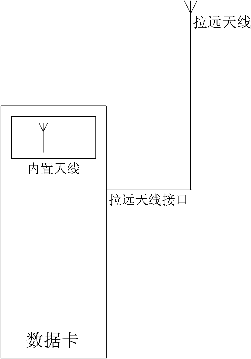
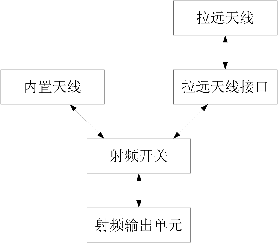
[0025] It is mentioned in related technologies that the remote antenna is an indispensable part of the whole solution, and the most stringent requirement for the remote antenna is that it has high gain, and the existing antennas have insufficient gain in applications. problem, making the antenna performance poor.
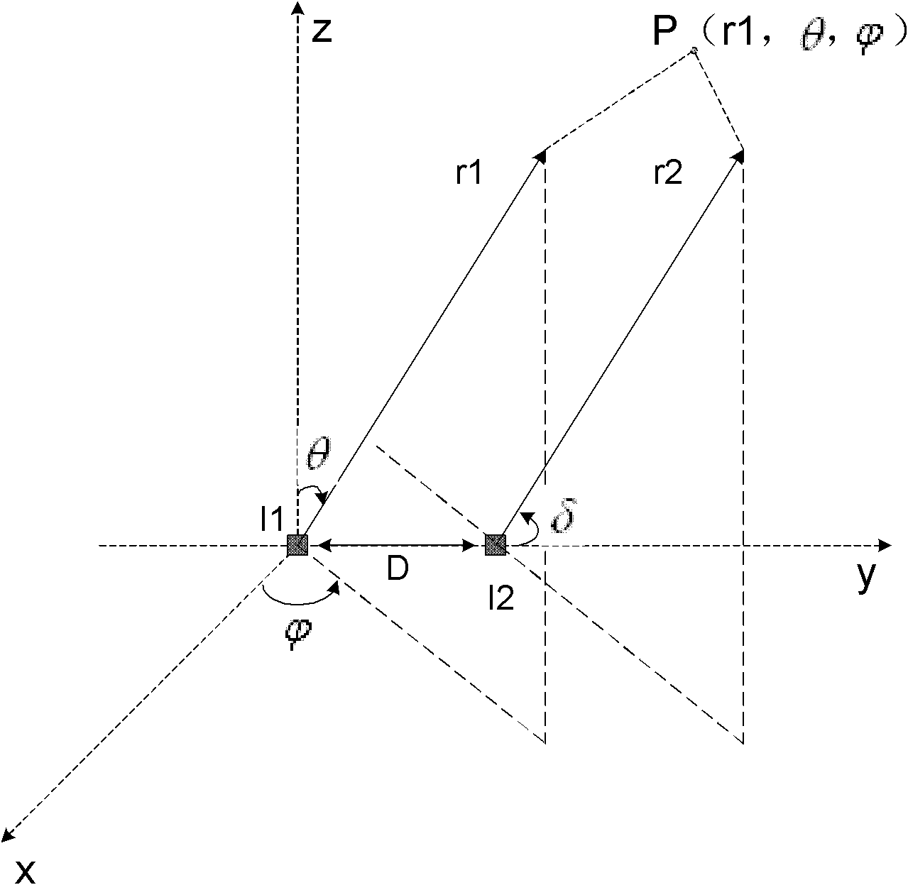
[0026] In order to solve the above technical problems, an embodiment of the present invention provides an antenna, which includes a plurality of unit antennas, and the plurality of unit antennas are arranged in a uniform straight line edge-fire ...
PUM
 Abstract
Description
Claims
Application Information
 - Generate Ideas
- Intellectual Property
- Life Sciences
- Materials
- Tech Scout
- Unparalleled Data Quality
- Higher Quality Content
- 60% Fewer Hallucinations
Browse by: Latest US Patents, China's latest patents, Technical Efficacy Thesaurus, Application Domain, Technology Topic, Popular Technical Reports.
© 2025 PatSnap. All rights reserved.Legal|Privacy policy|Modern Slavery Act Transparency Statement|Sitemap|About US| Contact US: help@patsnap.com