Reactive power compensation device for traction substation in electrified railway

A technology for traction substations and electrified railways, which is applied in reactive power compensation, circuit devices, reactive power adjustment/elimination/compensation, etc., and can solve problems such as inability to adapt to rapidly changing loads, inability to stabilize power supply voltage, and poor operational reliability, etc. problems, to achieve the effect of quickly adapting to load changes, fast construction speed, and short construction period

Active Publication Date: 2013-08-07
SHANXI KWONG FUK ENG
View PDF0 Cites 3 Cited by
  • Summary
  • Abstract
  • Description
  • Claims
  • Application Information

AI Technical Summary

Problems solved by technology

[0003] In order to solve the problems that the reactive power compensation device of the existing electrified railway traction power supply system cannot adapt to the rapidly changing load, the power supply voltage cannot be stabilized, the operation reliability is poor, and the cost is high, the invention provides a reactive power compensation device for the traction substation of the electrified railway device

Method used


Image

  • Reactive power compensation device for traction substation in electrified railway
  • Reactive power compensation device for traction substation in electrified railway
  • Reactive power compensation device for traction substation in electrified railway

Examples


Embodiment 1

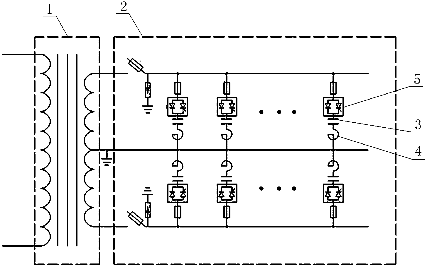
[0012] Such as figure 1 As shown, the reactive power compensation device of the electrified railway traction substation includes a special single-phase transformer 1 and a box power distribution device 2; several groups of contact devices, capacitors 3, and reactors 4 are installed in the box power distribution device 2 Reactive power compensation branches connected in series, both ends of each group of reactive power compensation branches are connected to the secondary side of the special single-phase transformer 1;

[0013] The secondary side of the special single-phase transformer 1 includes a set of windings with center taps; both ends of each set of reactive power compensation branches are connected to the windings with center taps;

[0014] The contact devices in each group of reactive power compensation branches are non-contact switches 5;

[0015] In specific implementation, a knife fuse switch (or circuit breaker), a zinc oxide arrester, and a fuse are connected in s...

Embodiment 2

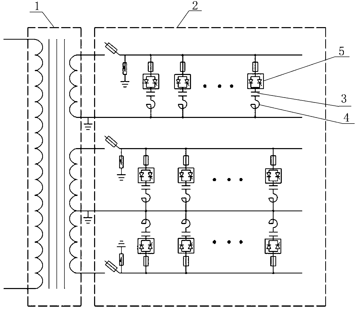
[0018] Such as figure 2 As shown, the reactive power compensation device of the electrified railway traction substation includes a special single-phase transformer 1 and a box power distribution device 2; several groups of contact devices, capacitors 3, and reactors 4 are installed in the box power distribution device 2 Reactive power compensation branches connected in series, both ends of each group of reactive power compensation branches are connected to the secondary side of the special single-phase transformer 1;

[0019] The secondary side of the special single-phase transformer 1 includes two sets of windings, one of which has a middle tap; the two ends of each set of reactive power compensation branches are respectively connected to the two sets of windings;

[0020] The contact devices in each group of reactive power compensation branches are non-contact switches 5;

[0021] In specific implementation, a knife fuse switch (or circuit breaker), a zinc oxide arrester, ...

Embodiment 3

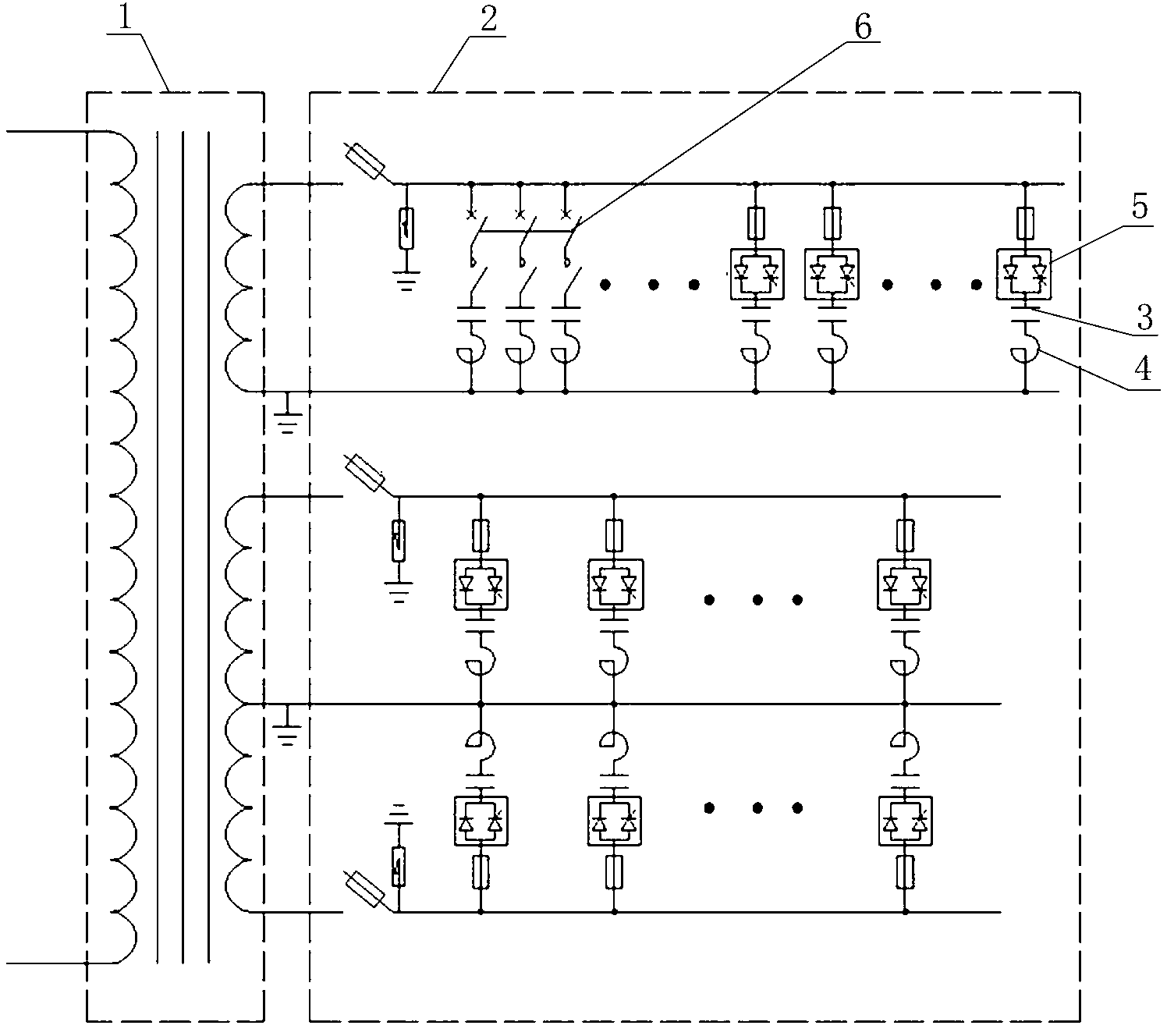
[0024] Such as image 3 As shown, the reactive power compensation device of the electrified railway traction substation includes a special single-phase transformer 1 and a box power distribution device 2; several groups of contact devices, capacitors 3, and reactors 4 are installed in the box power distribution device 2 Reactive power compensation branches connected in series, both ends of each group of reactive power compensation branches are connected to the secondary side of the special single-phase transformer 1;

[0025] The secondary side of the special single-phase transformer 1 includes two sets of windings, one of which has an intermediate tap; the two ends of each set of reactive power compensation branches are respectively connected to the two sets of windings;

[0026] The contact devices in several sets of reactive power compensation branches connected to the windings with intermediate taps are non-contact switches 5, and the contact devices in the remaining group...


PUM


Abstract

An electrified railway traction substation reactive power compensation apparatus. The apparatus comprises a special single-phase transformer (1) and a box-body power distribution apparatus (2). The box-body power distribution apparatus has arranged therein several sets of reactive power compensation branches formed by a contacting apparatus (5), capacitor (3), and an inductor (4) serially connected. The reactive power compensation apparatus is adaptive to rapidly changing load, has the advantages of stable power-supply voltage, great operation reliability, and low costs, and is applicable in reactive power compensation and harmonic suppression for electrified railway traction power-supply system.

Description

technical field [0001] The invention relates to a reactive power compensation technology for an electrified railway traction power supply system, in particular to a reactive power compensation device for an electrified railway traction substation. Background technique [0002] Single-phase 27.5kV power supply is generally used for electrified railway traction, which constitutes an asymmetrical load to the three-phase symmetrical power system. Electric traction uses rectifier locomotives, which consume lagging reactive power during operation and generate odd harmonic currents, resulting in low power factors of traction locomotives and causing harmonic pollution to the power system. In addition, the frequent start and stop of electric locomotive transposition operation and the randomness and out-of-load of locomotive load make the voltage sag at the PCC point of the power system very frequent, which seriously affects the power quality of the power supply grid and its normal op...

Claims


Application Information

Patent Timeline
Patent Type & Authority Patents(China)
IPC IPC(8): H02J3/18H02J3/01
CPCH02J3/1864H02J3/01B60M3/02H02J3/18Y02E40/30Y02E40/12H02J2310/40
Inventor 傅光祖史广福
Owner SHANXI KWONG FUK ENG
Why Eureka
Try Eureka