Electric network positive and negative reactive power compensation device

A compensation device, positive and negative technology, applied in the direction of reactive power compensation, reactive power adjustment/elimination/compensation, etc., can solve the inductive compensation of the power system, affect the normal operation of power equipment, and cannot adapt to unattended, etc. , to achieve the effects of saving manufacturing costs, suppressing harmonic currents, and reducing volume

Inactive Publication Date: 2009-12-02
HEBEI XUHUI ELECTRIC
View PDF0 Cites 4 Cited by
  • Summary
  • Abstract
  • Description
  • Claims
  • Application Information

AI Technical Summary

Problems solved by technology

However, at present, this kind of equipment cannot perform inductive compensation on the power consumption system, which will cause unnecessary losses on the transmission line or affect the normal operation of power consumption equipment for networks that require frequent inductive compensation
[0005] Connecting a synchronous condenser to the power line can provide both capacitive compensation and inductive compensation, but the synchronous condenser is a running device, which requires high maintenance and cannot adapt to unattended operation. At present, the synchronous condenser is used for unattended power grid The power compensation technology is an obsolete technology, and the static var compensation adjustment method is being vigorously developed at present.

Method used


Image

  • Electric network positive and negative reactive power compensation device
  • Electric network positive and negative reactive power compensation device

Examples


Embodiment 1

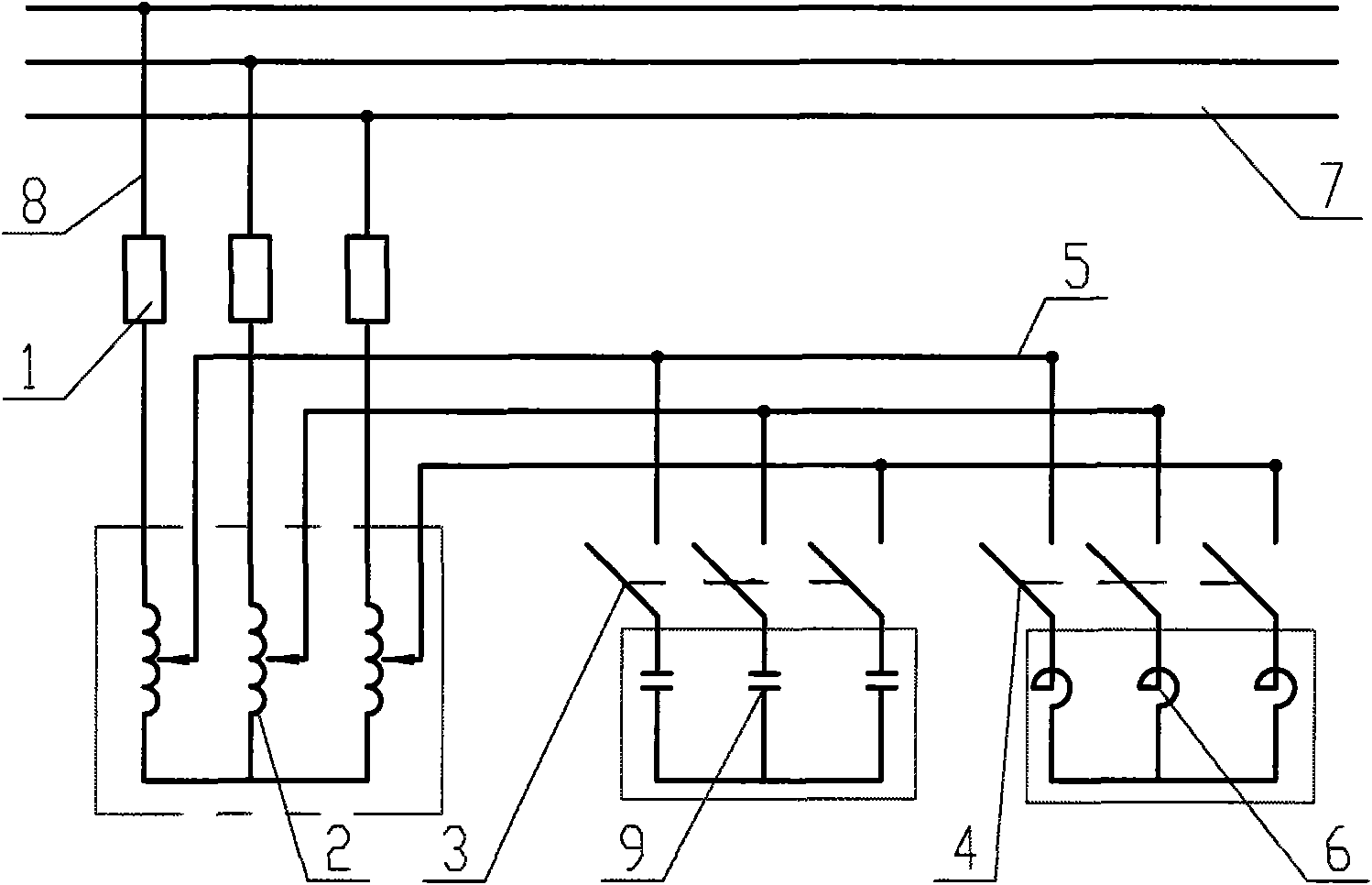
[0023] The power line of a power station is a 10kV three-phase system. The connection structure of the voltage reactive power compensation device of the present invention is as follows: figure 2 As shown, the inlet end of the voltage regulator 2 is connected to the three-phase conductor of the 10kV bus 7 through the circuit breaker 1 with three incoming wires 8 . Three outgoing lines 5 are drawn from the outgoing line end of the voltage regulator 2, and three sets of capacitors 9 and three sets of reactors 6 are respectively connected to the three outgoing lines 5, and three-phase switches 3 and 4 are respectively arranged between the capacitors 9, the reactors 6 and the outgoing lines 5 , the capacitor 9 and its switch 3 and the reactor 6 and its switch 4 form a parallel connection relationship. A reactor may also be connected between each capacitor and its switch 3 on the branch where the capacitor 9 is located in this embodiment.

Embodiment 2

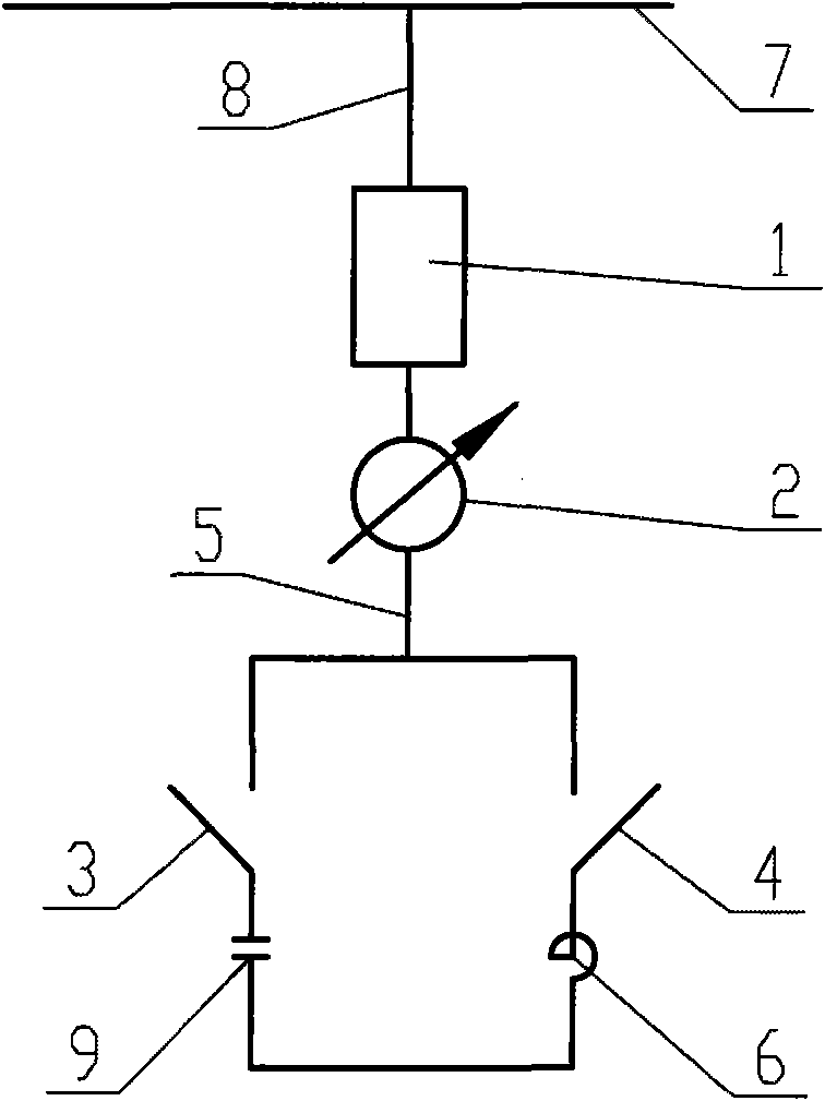
[0025] like figure 1 As shown, this embodiment is to regulate the single-phase system. The incoming terminal of the circuit breaker 1 is connected to the bus bar 7, the outgoing terminal of the circuit breaker 1 is connected to the incoming terminal of the autotransformer 2, and the outgoing terminal of the voltage regulator 2 is connected in parallel with a capacitor 9 and a reactor 6, and the capacitor 9 and the front of the reactor 6 are connected with switches 3 and 4 respectively. In this embodiment, an inductor may also be connected to the branch where the capacitor 9 is located.


PUM


Abstract

The invention discloses an electric network positive and negative reactive power compensation device which is applied to compensate the voltage and the reactive power of an electric network. The electric network positive and negative reactive power compensation device comprises a pressure regulator (2), one or a plurality of capacitors (9) and one or a plurality of reactors (6), wherein the line inlet end of the pressure regulator (2) is connected with a bus (7) by a circuit breaker (1); the capacitor (9) and the reactor (6) are connected with the line outlet end of the pressure regulator by one or a plurality of switches; after being connected with the reactor and the switch (4) connected in front of the reactor in parallel, the capacitor and the switch (3) connected in front of the capacitor are connected to the line outlet end of the pressure regulator (2); and the reactor is connected to the inside of a branch circuit of the capacitor in series. The invention provides a still reactive power compensation device which can supply capacitive compensation and inductive compensation, regulates the reactive power output of the capacitor and the reactor by regulating the output voltage of the pressure regulator, does not switch the capacitor at rated voltage, prevents serious overvoltage and inrush current and can realize finite order fine regulation in a total range from rated capacitive compensation capacity to rated inductive compensation capacity.

Description

technical field [0001] The invention relates to a grid reactive power compensation device, which is applied to the compensation of grid voltage and reactive power. Background technique [0002] The general electrical equipment in the power grid is an inductive load, while the line itself is a capacitive load. Reactive power in the grid exists all the time, and reactive power compensation and control devices are used in large and small substations or power usage places. Under normal circumstances, the entire grid system is inductive, and capacitive compensation is required for the grid at this time; but when there are fewer users and light loads, the entire grid system presents a capacitive state, and inductive compensation is required at this time. [0003] Since the general electrical equipment in the power grid is an inductive load, the general reactive power compensation device is directly connected to the capacitor bank in the power line, and is controlled by a computer...

Claims


Application Information

Patent Timeline
Patent Type & Authority Applications(China)
IPC IPC(8): H02J3/18
CPCY02E40/30H02J3/1828H02H9/002
Inventor 李瑞桂吴洪伟张旭辉
Owner HEBEI XUHUI ELECTRIC
Why Eureka
Try Eureka