System and method for optimizing rotor vibration compensation through using variable-step variable-angle search genetic algorithm

A technology of rotor vibration and genetic algorithm, applied in the control system, torque ripple control, vector control system, etc., can solve the problem that the rotor cannot be positioned with high precision

Active Publication Date: 2021-05-14
JIANGSU UNIV
View PDF7 Cites 2 Cited by
  • Summary
  • Abstract
  • Description
  • Claims
  • Application Information

AI Technical Summary

Problems solved by technology

[0005] The purpose of the present invention is to overcome the shortcomings of vibration and eccentricity of the rotor when the bearingless permanent magnet synchronous motor is working, especially when the motor is working at different speeds, the rotor cannot be positioned with high precision due to offset and vibration. , a rotor vibration compensation system and rotor vibration compensation method optimized based on variable step size

Method used


Image

  • System and method for optimizing rotor vibration compensation through using variable-step variable-angle search genetic algorithm
  • System and method for optimizing rotor vibration compensation through using variable-step variable-angle search genetic algorithm
  • System and method for optimizing rotor vibration compensation through using variable-step variable-angle search genetic algorithm

Examples


Embodiment Construction

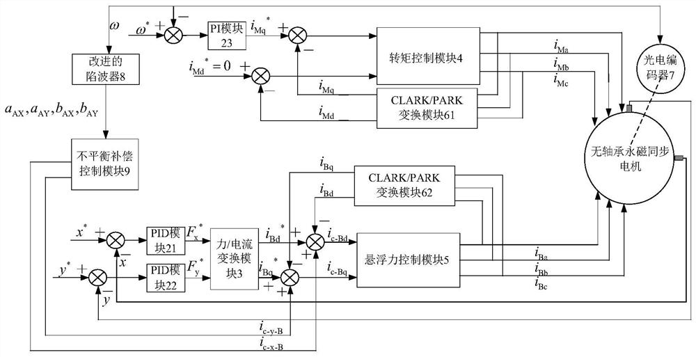
[0028] see figure 1The variable step length and variable angle search genetic algorithm optimization rotor vibration compensation system of the present invention (hereinafter referred to as the vibration compensation system) includes a torque control part, a suspension force control part, an improved wave trap 8 and an unbalance compensation module 9 . Among them, the torque control part and the levitation force control part are conventional control parts of the bearingless permanent magnet synchronous motor control system. The torque control part is composed of the torque control module 4, the CLARK / PARK transformation module 61 and the PI module 23, and the suspension force control part is composed of the suspension force control module 5, the CLARK / PARK transformation module 62, the force / current transformation module 3 and two PID modules 21, 22 are composed.

[0029] For the torque control part, the three-phase torque control current i is output by the torque control mod...


PUM


Abstract

The invention discloses a system and a method for optimizing rotor vibration compensation through using variable-step variable-angle search genetic algorithm of a bearingless permanent magnet synchronous motor. The method comprises the steps that a rotating speed serves as the input of an improved wave trap, and sine and cosine coefficients of vibration signals with the same frequency as a rotor in the x and y directions of the rotor are output by the improved wave trap, the sine coefficient and the cosine coefficient are input into an unbalance compensation module, the unbalance compensation module compares the total vibration amplitude with a vibration target value, if the total vibration amplitude is larger than the vibration target value, compensation control is conducted on rotor vibration through adopting a variable-step-size variable-angle search method, when the vibration of the next step is smaller than that of the previous step, the step size and the angle are increased, and when the vibration of the next step is larger than that of the previous step, the angle is changed by 90 degrees and the step length is changed into the initial search step length. Therefore, the search angle and direction are continuously changed to obtain an identification coefficient, and the optimal compensation current is calculated; and a response speed of rotor vibration compensation is accelerated, and rotor vibration compensation can be carried out under the condition that the motor runs at a full rotating speed.

Description

technical field [0001] The invention relates to the control technology of a bearingless permanent magnet synchronous motor, in particular to the rotor offset and vibration control of the bearingless permanent magnet synchronous motor, which improves the traditional search algorithm with fixed step length and fixed angle, and performs compensation control for rotor unbalance. Background technique [0002] The bearingless permanent magnet synchronous motor is a kind of motor that uses the levitation winding to provide the levitation force, and the torque winding provides the torque to make the rotor levitate and rotate. Therefore, the bearingless permanent magnet synchronous motor has no friction, no wear, no lubrication, high speed and high speed. Accuracy and other advantages, it has important application value in high-tech fields such as centrifuges, sealed pumps, turbomolecular pumps, flywheel energy storage, semiconductor industry, life sciences and aerospace. For the rot...

Claims


Application Information

Patent Timeline
IPC IPC(8): H02P21/05H02P6/10
CPCH02P21/05H02P6/10H02P2207/05Y02E60/16
Inventor 朱熀秋周锴
Owner JIANGSU UNIV
Why Eureka
Try Eureka