Check patentability & draft patents in minutes with Patsnap Eureka AI!

Antenna calibration method and device

An antenna calibration and antenna technology, applied in the directions of antenna, correct operation test, electrical components, etc., can solve the problems of prolonged calibration period, inability to real-time, and inability to monitor the differences of multiple RF channels, achieving simple implementation and small changes. Effect

Active Publication Date: 2014-05-21
WUHAN HONGXIN TELECOMM TECH CO LTD +1
View PDF5 Cites 0 Cited by
  • Summary
  • Abstract
  • Description
  • Claims
  • Application Information

AI Technical Summary

Problems solved by technology

[0009] (1) The accuracy of feedback calibration cannot be achieved, resulting in the fact that there are still differences between multiple RF channels after calibration and cannot be monitored
[0010] (2) The calibration cycle cannot be adjusted in real time according to the calibration accuracy. When the RF channel changes rapidly, the calibration cycle is shortened, and when the RF channel changes slowly, the calibration cycle is lengthened.

Method used


Image

  • Antenna calibration method and device
  • Antenna calibration method and device
  • Antenna calibration method and device

Examples


Embodiment Construction

[0022] Embodiments of the present invention are described in detail below, examples of which are shown in the drawings, wherein the same or similar reference numerals designate the same or similar elements or elements having the same or similar functions throughout. The embodiments described below by referring to the figures are exemplary only for explaining the present invention and should not be construed as limiting the present invention.

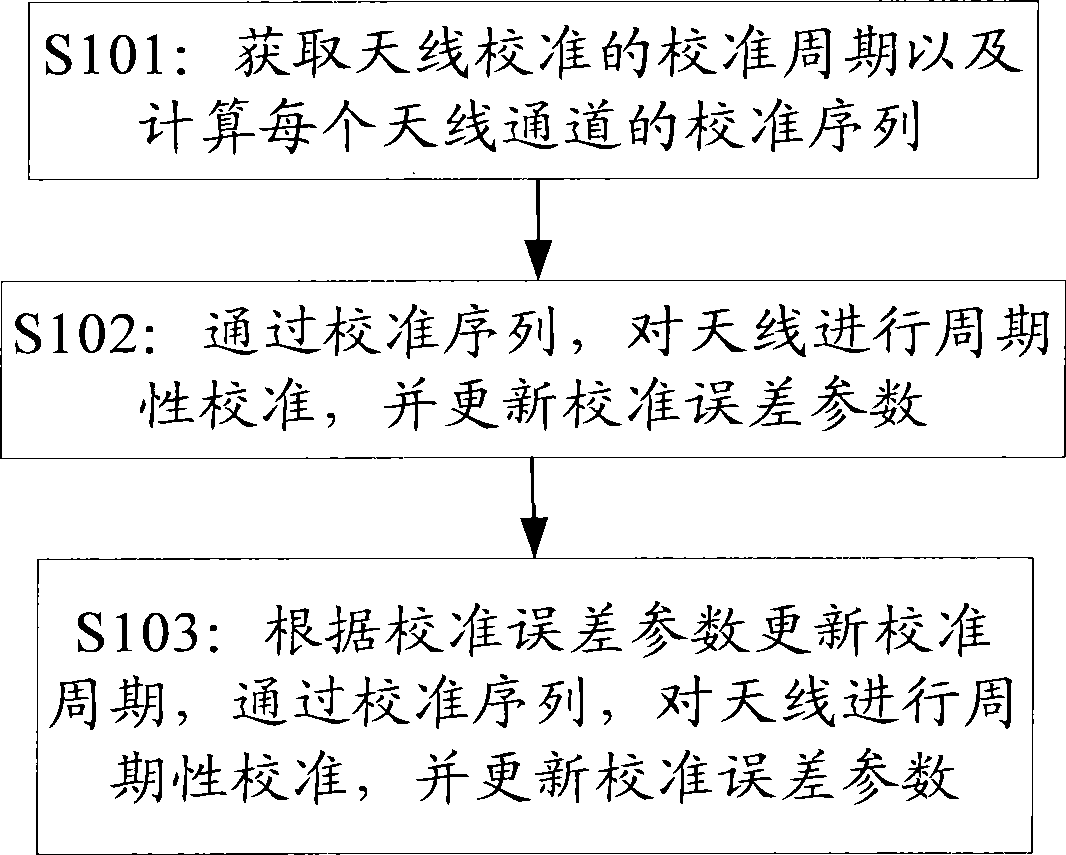
[0023] In order to achieve the purpose of the present invention, the present invention discloses a method for antenna calibration, including the following steps: obtaining the calibration cycle T_i of antenna calibration and calculating the calibration sequence of each antenna channel, the calibration cycle T_i is a predetermined threshold value A ; Through the calibration sequence, periodically calibrate the antenna with the T_i period, and update the calibration error parameter; according to the calibration error parameter and the T_i, ...


PUM


Abstract

A method for antenna calibration is provided, which includes the following steps: obtaining an updated calibration period T_i after the last time of antenna calibration (S301), calculating a calibration sequence of each antenna channel in the calibration period T_i (S302); according to the calibration sequence of each antenna channel, calibrating each antenna based on the calibration period T_i, and calculating a calibration error parameter (S303); and according to the obtained calibration error parameter, updating the calibration period T_i, and using the updated calibration period T_i for the next time of antenna calibration (S304). The technical solutions provided in the present invention, can monitor difference variety of radio channels in real time by the calibration error parameter, and reflect the calibration precision in real time by the reported calibration error parameter. Moreover, the technical solutions provided in the present invention, can adjust the calibration period in real time according to the calibration error parameter, and timely execute rational antenna calibration according to the calibration precision status.

Description

technical field [0001] The present invention relates to the field of mobile communication, in particular, the present invention relates to a method and device for antenna calibration. Background technique [0002] Mobile and broadband have become the development direction of modern communication technology. How to eliminate the influence of co-channel interference, multiple access interference and multipath fading has become the main factor that people consider when improving the performance of wireless mobile communication systems. In recent years, smart antenna technology has become a research hotspot in the field of mobile communication. [0003] Smart antenna technology brings great advantages to mobile communication systems. For example, when using smart antennas, other baseband digital signal processing technologies, such as joint detection, interference cancellation, etc., are used in combination. The sum of the received signals, if the maximum power combining algor...

Claims


Application Information

Patent Timeline
Patent Type & Authority Patents(China)
IPC IPC(8): H04L1/24
CPCH01Q3/267
Inventor 李传军孙长果
Owner WUHAN HONGXIN TELECOMM TECH CO LTD
Features
  • R&D
  • Intellectual Property
  • Life Sciences
  • Materials
  • Tech Scout
  • Unparalleled Data Quality
  • Higher Quality Content
  • 60% Fewer Hallucinations
Learn More