Calibration method of magnetic sensor array

A magnetic sensor and calibration method technology, applied in the field of magnetic target positioning, can solve the problems of prolonging the experiment cycle, reducing calibration accuracy, and low calibration efficiency, and achieving the effects of improving calibration efficiency, prolonging calibration time, and shortening calibration cycle

Pending Publication Date: 2022-06-24
HARBIN INST OF TECH
View PDF0 Cites 1 Cited by
  • Summary
  • Abstract
  • Description
  • Claims
  • Application Information

AI Technical Summary

Problems solved by technology

The position deviation of the test point makes the baseline distance between the magnetic sensors and the design value have an error, which will cause the calculation error of the magnetic field gradient
The solid line in the figure is the ideal baseline, and the dotted line is the actual baseline. The position deviation of the test points makes the baselines no longer orthogonal to each other, which will cause calculation errors of the magnetic field tensor.
In addition, the existing research is to correct the output of the magnetic sensor to the coordinate system of the reference magnetic sensor, but the coordinate system o1-x1y1z1 of the reference magnetic sensor (assuming that magnetic sensor 1 is the reference magnetic sensor) is different from the standard coordinate system of the magnetic positioning system There is still a misalignment error between o-xyz, called output misalignment error
Therefore, the error parameters of the magnetic sensor array that can be calibrated by traditional calibration methods are incomplete
[0006] 2. The calibration accuracy of the magnetic sensor array is limited by the non-uniformity and instability of the geomagnetic field, which cannot be further improved
The manual rotation of the turntable not only makes the hard and soft magnetic interference unstable and difficult to compensate, but also prolongs the experiment period and aggravates the instability and non-uniformity of the geomagnetic field
Therefore, the use of the turntable not only reduces the calibration accuracy, but also makes the calibration efficiency not high

Method used


Image

  • Calibration method of magnetic sensor array
  • Calibration method of magnetic sensor array
  • Calibration method of magnetic sensor array

Examples


specific Embodiment

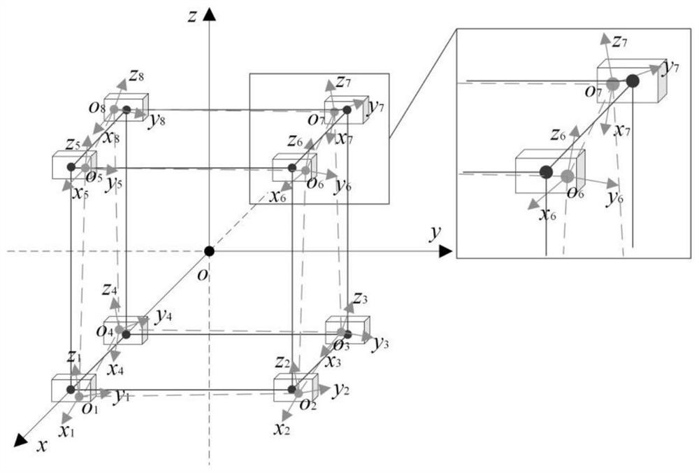
[0074] Take the magnetic sensor array structure as a regular six-sided structure, such as Figure 4 As shown, the number of sensors is 8, and the baseline distance D is 0.032m. According to the specifications of Mag-03, the given scale factor error is ±0.5%, the non-orthogonal error is ±0.1°, the zero offset is ±5nT, the misalignment error is ±2°, and the test point position deviation is ±2mm.

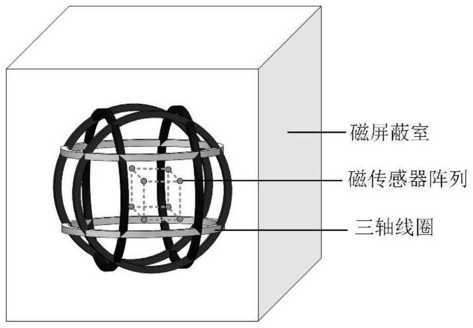
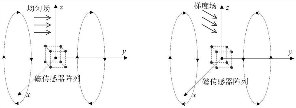
[0075] The uniform field-gradient field composite coil used to calibrate the magnetic sensor array adopts a three-axis square coil structure. There are four coils with the same side length on a single axis. The coil structure of the y-axis is as follows: Figure 5 shown. The structures of other axial coils are similar, and details are not repeated here. The magnetic shielding room is a regular hexahedron structure with a side length of 1.85m, and the standard deviation of the magnetic noise is 0.1nT. During calibration, the number of current groups passed through is 32 groups. When...


PUM


Abstract

The invention discloses a calibration method of a magnetic sensor array, and belongs to the technical field of magnetic target positioning. The calibration method of the magnetic sensor array comprises the following steps of S100, electrifying coaxial coils in the same direction to enable a uniform field-gradient field composite coil to be in a uniform field mode, and calibrating a self error parameter and an output misalignment error parameter of the magnetic sensor array by utilizing the uniformity of a coil magnetic field; and S200, reversely electrifying the coaxial coils to enable the uniform field-gradient field composite coil to be in a gradient field mode, and calibrating the position deviation of the test points of the magnetic sensor array by using the coordinate coordination between the two modes and the spatial resolution of the gradient magnetic field. According to the invention, background magnetic interference is eliminated, the calibration precision is further improved, and the calibration efficiency is greatly improved. Meanwhile, the problem that two kinds of error parameters including test point position deviation and output misalignment cannot be calibrated is solved, and a magnetic sensor array calibration system is further improved.

Description

technical field [0001] The invention relates to a calibration method of a magnetic sensor array, belonging to the technical field of magnetic target positioning. Background technique [0002] Magnetic positioning technology is a target positioning technology based on magnetic field. It has the advantages of all-weather, high speed and high precision. It shows its unique advantages and application prospects in many fields such as geophysics and biomedicine. When positioning and navigating surgical robots, magnetic positioning technology is unobstructed and less expensive than optical tracking. Magnetic localization is safer, less expensive, and more efficient than radioactive CT and expensive MRI for tracking wireless capsule endoscopy, tongue movement, and magnetic drug labeling. [0003] Magnetic sensor array is the application basis of magnetic positioning technology, and the accuracy of its magnetic field measurement will directly affect the positioning accuracy of magne...

Claims


Application Information

Patent Timeline
Patent Type & Authority Applications(China)
IPC IPC(8): G01R33/00G01R35/00G06F17/16
CPCG01R33/0094G01R33/0023G01R35/005G06F17/16
Inventor 潘东华林生鑫靳崇渝王一丁王矜婷王雷李立毅
Owner HARBIN INST OF TECH
Why Eureka
Try Eureka