Apparatus and process for producing absorbent

An absorber and gas technology, which is applied in the field of absorber devices, can solve problems such as hindering the uniform dispersion of superabsorbent polymer 5, and achieve the effect of reducing the impact

Active Publication Date: 2011-06-29
UNI CHARM CORP
View PDF6 Cites 8 Cited by
  • Summary
  • Abstract
  • Description
  • Claims
  • Application Information

AI Technical Summary

Problems solved by technology

This intruded external air causes turbulence such as eddy currents inside the duct 31, and as a result,

Method used


Image

  • Apparatus and process for producing absorbent
  • Apparatus and process for producing absorbent
  • Apparatus and process for producing absorbent

Examples


Embodiment approach

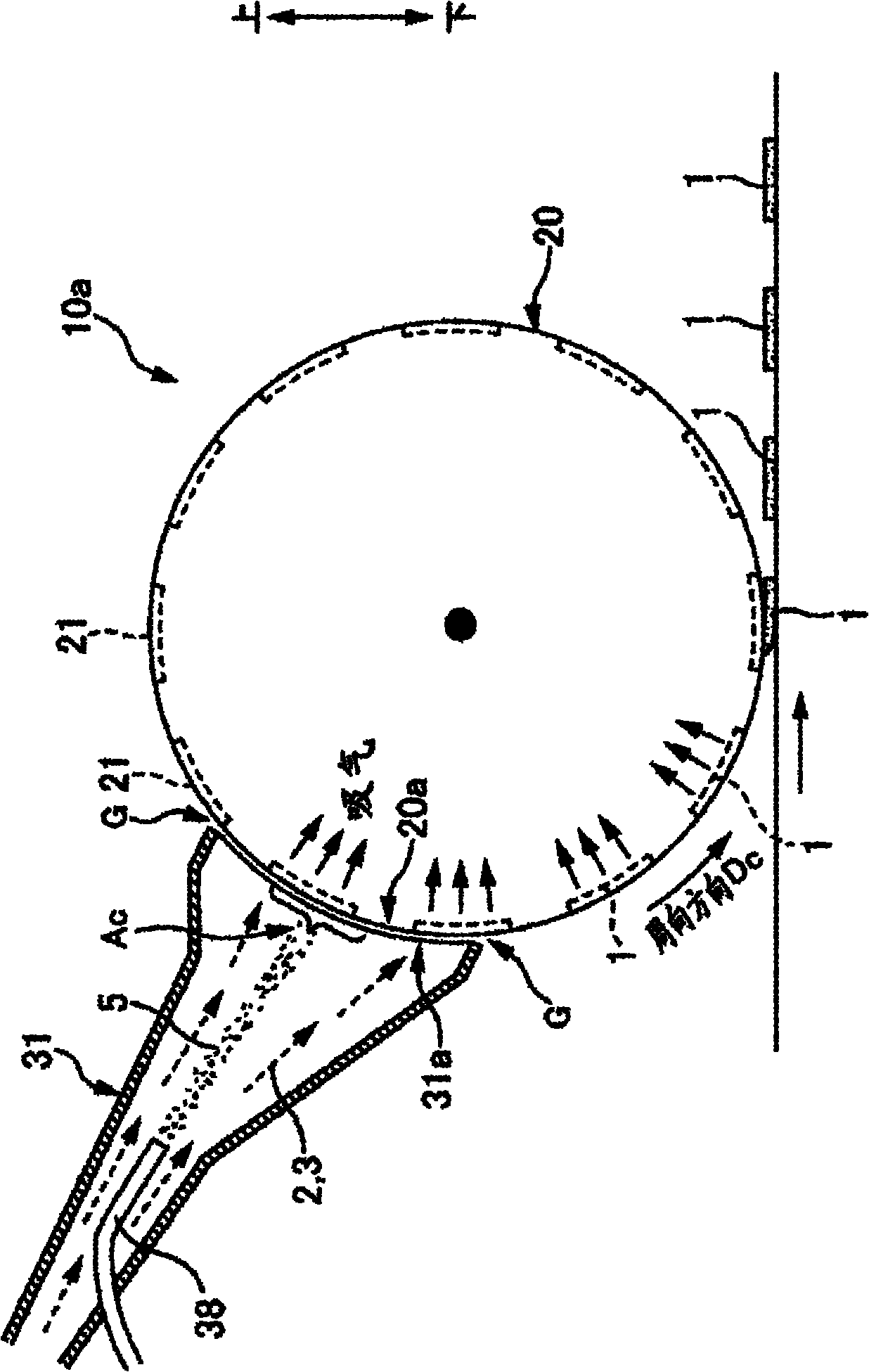
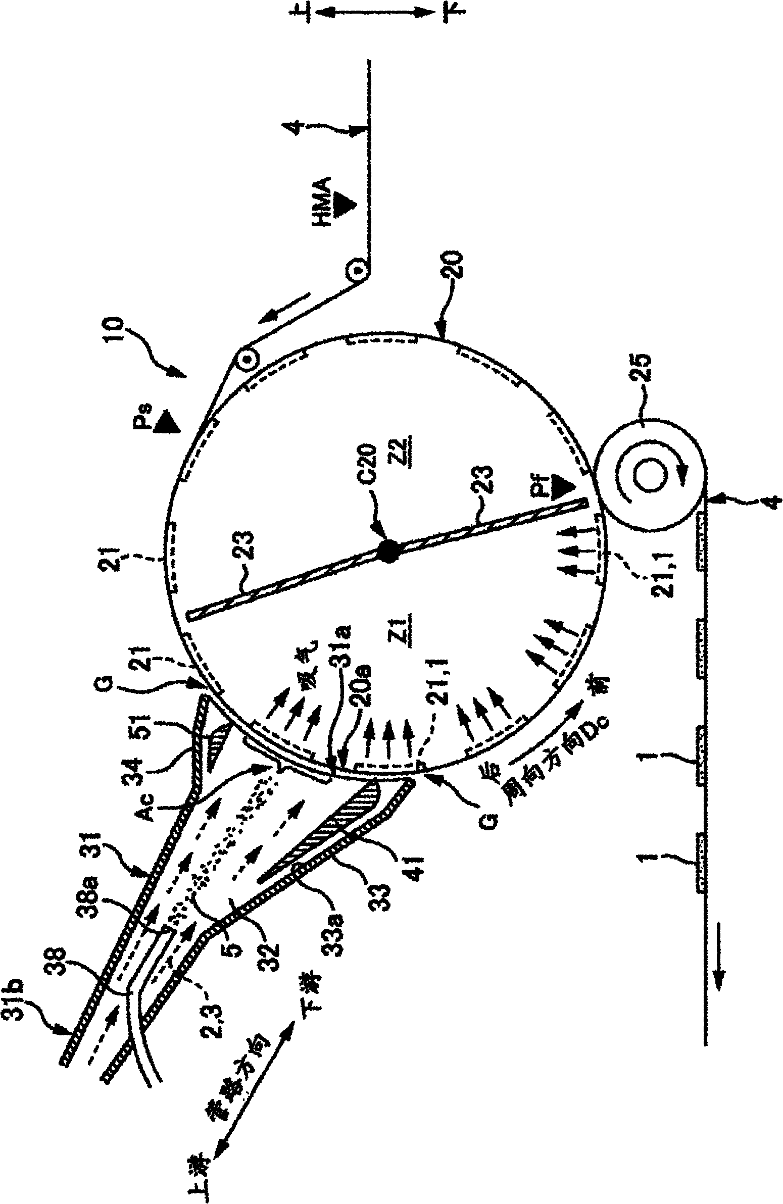
[0089] figure 2 is a side view of the apparatus 10 for manufacturing the absorbent body 1 according to the present embodiment. exist figure 2 In , only the portion of the conduit 31 of the manufacturing device 10 is shown in vertical section.

[0090] The apparatus 10 for manufacturing the absorbent body 1 according to the present embodiment is a so-called fiber lamination apparatus that layers pulp fibers 2 as liquid-absorbent fibers to form the absorbent body 1 . In terms of main structure, this manufacturing apparatus 10 includes: (1) a rotating drum 20 (corresponding to a prescribed member) which continues around a horizontal axis C20 in one direction (for example, counterclockwise) of the circumferential direction Dc; (2) the conduit 31 that discharges the pulp containing pulp from the spreading port 31a (corresponding to the opening) provided at a predetermined position of the rotary drum 20 in the circumferential direction Dc to the outer peripheral surface 20a of t...


PUM


Abstract

The present invention relates to a production apparatus which includes a rotating drum (20) having a die (21) formed therein and in which, when the die (21) passes through the position of a duct (31), the drum (20) draws a gas (3) through suction holes formed in the bottom of the die (21), whereby liquid-absorbing fibers (2) and a highly absorbing polymer (5) which are contained in the gas (3) are stacked in the die (21) to mold an absorbent (1). The duct (31) includes a duct inner-wall part (41) disposed therein so as to face the inner surface (33a) of a wall part (33) of the duct (31) and to leave a space (S3) therebetween. Outside air which has come into the duct (31) through the gap (G) between the peripheral surface (20a) of the rotating drum (20) and the opening (31a) of the duct (31) is controlled by the duct inner-wall part (41) so as not to flow into a central area (Ac) of the duct (31).

Description

technical field [0001] The present invention relates to an apparatus and a method for manufacturing absorbent bodies of absorbent articles such as disposable diapers. Background technique [0002] As examples of absorbent articles that absorb liquid, disposable diapers, sanitary napkins, and the like are used. These absorbent articles include an absorbent body 1 manufactured by forming pulp fibers into a predetermined shape. [0003] The absorbent body 1 is formed by a fiber laminating device 10a on a production line. figure 1 is a side view of the fiber lamination device 10a partially shown in vertical section. The fiber lamination device 10 a mainly includes a rotary drum 20 rotating in the circumferential direction Dc, and a concave molding die 21 is formed on the outer peripheral surface 20 a of the rotary drum 20 . The bottom of the molding die 21 is configured to allow air intake. Furthermore, the spraying port 31a of the duct 31 is provided facing the outer periph...

Claims


Application Information

Patent Timeline
IPC IPC(8): A61F13/15A61F13/472A61F13/49D04H1/72A61F13/20A61F13/53
CPCD04H1/72A61F13/15658A61F13/15626A61F2013/530489A61F13/53D06B23/30
Inventor 矢野尊敬铃木周
Owner UNI CHARM CORP
Why Eureka
Try Eureka