Molding die, and molding die manufacturing method

A manufacturing method and a technology for forming a mold, which are applied in the manufacture of optical record carriers, recording/reproducing by optical methods, instruments, etc., and can solve the problems of deterioration, easy deformation and formability of molds, etc.

Active Publication Date: 2014-12-17
KURARAY CO LTD
View PDF7 Cites 0 Cited by
  • Summary
  • Abstract
  • Description
  • Claims
  • Application Information

AI Technical Summary

Problems solved by technology

[0014] In the case of molding using a mold (the above-mentioned mold 40) having concavities and convexities reflecting the fine concavo-convex structure of the master mold on the back surface, the problem that the mold is easily deformed due to the concavities and convexities on the back surface and the formability is significantly deteriorated, and the molded product is The problem that transfer marks corresponding to the unevenness of the back side of the mold occur on the surface side of the mold

Method used


Image

  • Molding die, and molding die manufacturing method
  • Molding die, and molding die manufacturing method
  • Molding die, and molding die manufacturing method

Examples


Embodiment 1

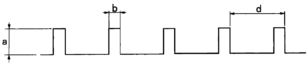
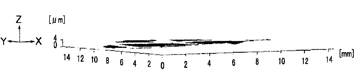
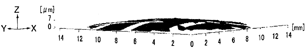
[0100] Produced on a 1mm thick flat SUS substrate by photolithography using near ultraviolet rays image 3 and Figure 4 For the resist structure 11 of the size shown, only 20 μm of Ni was deposited on the SUS substrate by Ni electroforming. Then, Ni was vacuum vapor-deposited to form a conductive film on the substrate formed in the second step, and then Ni electroforming was performed to deposit Ni to a thickness of 500 μm.

[0101] After the resist is removed, the forming die 10 is obtained. Oxygen plasma treatment is applied to the surface of the molding die to perform molding.


PUM

PropertyMeasurementUnit
heightaaaaaaaaaa
heightaaaaaaaaaa

Abstract

Disclosed is a molding die having a molding face, to which a finely irregular surface structure based on a mother mold is transferred, so that the molding die is durable and can retain the flatness of the molding face.  Also disclosed is a method for manufacturing molding dies (10 and 12) having the finely irregular surface on a molding face (10a).  The method comprises: a mother mold forming step of applying a finely-ridged resist structure (11) based on a resist to an energization part (12a) by using an energization substrate (12) having the energization part (12a) on at least one surface thereof, to thereby form a mother mold (10A); a metal structure forming step of depositing a metal having a thickness corresponding to the height of the resist structure (11), on the energization part (12a), to thereby form a metal structure (13); an energization film forming step of forming an energization film (14) on the surface of the resist structure (11); a reinforcing layer forming step of forming a reinforcing layer (15) on the energization film (14) by a plating treatment; and a mother mold removing step of removing the mother mold (10A) to thereby form the mold having the finely irregular patterns based on the metal structure (13).

Description

technical field [0001] The present invention relates to a forming die and a method for manufacturing the forming die. Background technique [0002] For display components such as liquid crystals, recording media such as DVDs, mobile phone components, biochips such as DNA chips, and the like, molded articles in which a fine concave-convex structure centered on the micron order or submicron order are used. In addition, as a material for forming these molded articles, resin, silicon, or glass is used. [0003] Examples of methods for forming such a resin molded article having a fine uneven structure include injection molding, nanoimprint molding, emboss molding, roll transfer molding, and the like. In addition, dry etching and wet etching of silicon can be exemplified as a method of forming a silicon molded product in which a fine uneven structure is formed. Furthermore, as a method of forming the glass molded article in which the fine uneven|corrugated structure was formed, ...

Claims


Application Information

Patent Timeline
Patent Type & Authority Patents(China)
IPC IPC(8): B29C33/38G11B7/26
CPCG11B7/261B29C33/3878B29C33/38G11B7/26
Inventor 田崎刚福田始弘
Owner KURARAY CO LTD
Why Eureka
Try Eureka