Vehicle seat slide device

A sliding device, vehicle technology, applied to vehicle seats, special positions of vehicles, movable seats, etc., can solve problems such as productivity problems, deformation, damage to operating handles, etc., to save space, reduce the number of parts, and simplify installation Effect

Inactive Publication Date: 2011-06-29
AISIN SEIKI KK
View PDF7 Cites 4 Cited by
  • Summary
  • Abstract
  • Description
  • Claims
  • Application Information

AI Technical Summary

Problems solved by technology

Therefore, the low-rigidity operating handle may be damaged or deformed in the middle of the assembly work in the workshop, which may cause problems in terms of productivity.

Method used


Image

  • Vehicle seat slide device
  • Vehicle seat slide device
  • Vehicle seat slide device

Examples


Embodiment Construction

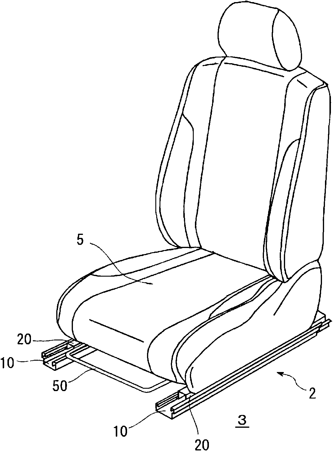
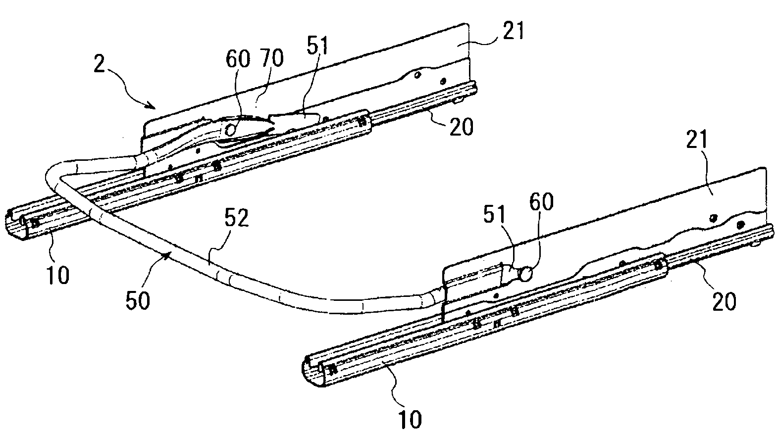
[0033] Hereinafter, embodiments of the vehicle seat sliding device according to the present invention will be described with reference to the drawings. figure 1 is a perspective view showing a vehicle seat sliding device assembled in a vehicle seat, figure 2 It is a perspective view showing the seat sliding device for a vehicle. The vehicle seat sliding device 2 is provided with: a pair of left and right lower rails 10 fixed to the vehicle floor 3; a pair of left and right upper rails 20 fixed to the vehicle seat 5; Handle 50.

[0034] Such as Figure 6 As shown, a pair of lower guide rails 10 has: a bottom wall portion 11; a pair of side wall portions 12 extending upward from both ends of the bottom wall portion 11; The lower flange wall portion 13. The lower rail 10 is formed by bending a single plate, and has a substantially U-shaped cross section.

[0035] The upper rail 20 has: a vertical wall portion 21 as a vertical wall; a pair of bottom wall portions 22 bent out...


PUM


Abstract

A vehicle seat slide device provided with an operation handle uses a reduced number of parts, occupies a reduced space, and is produced with increased productivity. An operation handle (50) is provided with a holding section (52), an application end section (53) for operating a lock-unlock mechanism (30), a shaft support section (57) located between the application end section (53) and the holding section (52) and formed flat so as to be parallel to a vertical wall (21), and a pivot support shaft (60) projecting to the shaft support section (57) in the direction of the center of pivoting of the operation handle (50). The vertical wall (21) has an open holding hole (21a) which has the front side open and in which the pivot support shaft (60) is inserted from an open portion so as to be supported at an inner end section (21c), and also has a holding member (70) for holding the pivot support shaft (60) at the open holding hole (21a).

Description

technical field [0001] The present invention relates to a seat sliding device for a vehicle. The seat sliding device for a vehicle comprises: a lower rail fixed to a vehicle floor; an upper rail supported on a vehicle seat and supported by the lower rail as Able to move forward and backward; and a locking mechanism, which is used to lock the front and rear movement of the upper guide rail relative to the lower guide rail, and the locking mechanism is operated by a handle. Background technique [0002] According to the vehicle seat sliding device of Patent Document 1, the lock lever is pivotally supported on the vertical wall of the upper rail in a rotatable manner, and the lock lever is connected to the top end of the inner lower flange portion provided on the lower rail by the action of the lock spring. The claws of the upper rail are locked with respect to the lower rail. On the other hand, the handle mounting part integrally formed with the lock lever is provided near th...

Claims


Application Information

Patent Timeline
Patent Type & Authority Applications(China)
IPC IPC(8): B60N2/08
CPCB60N2/085B60N2/0887B60N2/071B60N2/0715B60N2/0825
Inventor 山田幸史后藤直希矶部晋也
Owner AISIN SEIKI KK
Why Eureka
Try Eureka