Single liftable compound pipe

A composite tube and composite belt technology, which is applied in the direction of lifting frame and lifting device, etc., can solve the problems of small equipment height and so on.

Inactive Publication Date: 2011-07-06
郑仙丽
View PDF5 Cites 6 Cited by
  • Summary
  • Abstract
  • Description
  • Claims
  • Application Information

AI Technical Summary

Problems solved by technology

At present, the lifting table is usually realized by hydraulic drive and screw drive, each with its own advantages and disadvantages: 1) The same stroke is generally the minimum equipment height occupied by the

Method used


Image

  • Single liftable compound pipe
  • Single liftable compound pipe
  • Single liftable compound pipe

Examples


Embodiment Construction

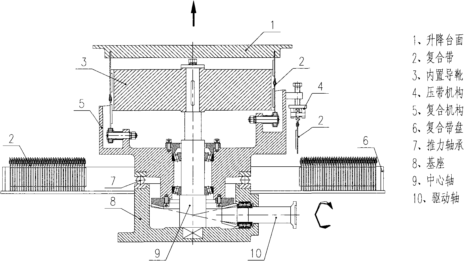
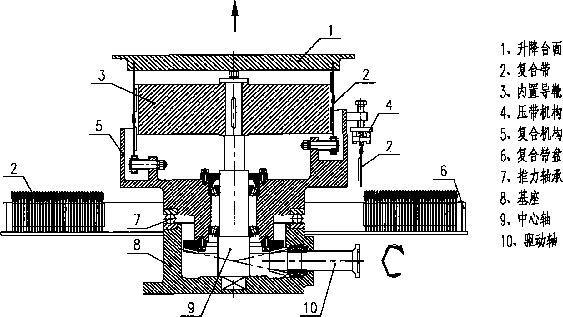
[0015] The following will be described by taking a single liftable right-handed composite pipe as an example (the specific implementation of a single left-handed composite pipe that can be lifted is the same). figure 1 The cross-sectional view of a single liftable composite pipe is shown.

[0016] A single lifting composite pipe can be driven by external power (reducer output shaft, ground shaft, etc.) to drive the drive shaft 10 mounted on the base 8 to rotate clockwise, and drive the composite mechanism 5 mounted on the thrust bearing 7 to operate. Clockwise movement. The composite belt 2 is loaded by the bearing on the composite mechanism 5. When the composite mechanism 5 moves clockwise, the built-in guide shoe 3 and the base 8 are fixed by the central shaft 9 and cannot rotate. Therefore, the guide block on the composite belt 2 can only Moving upward along the built-in guide shoe 3, the composite tape 2 is continuously output from the composite tape reel 6, and is accura...


PUM


Abstract

The invention provides lifting equipment, which has a self-locking function and low height. In particular, a compound band 2 forms the rising motion of a single liftable compound pipe through a combined motion of a compound mechanism 5 and forms the falling motion of the single liftable compound pipe through decomposed motion of the compound mechanism 5. The single liftable compound pipe can be kept at the stopped position for long time and has shallow foundation pit.

Description

technical field [0001] The invention relates to a vertical lifting mechanism, which is similar to a jack, and the external load acts vertically on the upper end of the equipment. Background technique [0002] The lifting platform with a certain stroke has a corresponding minimum clear height, which is the height occupied by the equipment itself. At present, lifting platforms are usually realized in two ways: hydraulic drive and screw drive, each with its own advantages and disadvantages: 1) The hydraulic scissor lift generally occupies the smallest equipment height for the same stroke. The hydraulic scissor lift table requires multiple hydraulic cylinders to work synchronously. Since multiple hydraulic cylinders can only be synchronized softly by the synchronous valve, rigid synchronization cannot be achieved, so it is difficult to achieve precise synchronization. When the lifting platform stops at a certain position, there are height differences at different positions of t...

Claims


Application Information

Patent Timeline
IPC IPC(8): B66F7/28
Inventor 郑仙丽
Owner 郑仙丽
Why Eureka
Try Eureka