Magnetic rotor structure and power-driven switching valve

An electric switching and magnetic rotor technology, applied in valve details, multi-port valves, valve devices, etc., can solve the problems affecting the normal opening of the electric switching valve, pressure difference, etc., and achieve the effect of eliminating the pressure difference and ensuring the normal valve opening.

Inactive Publication Date: 2011-07-06
ZHEJIANG SANHUA CO LTD
View PDF1 Cites 8 Cited by
  • Summary
  • Abstract
  • Description
  • Claims
  • Application Information

AI Technical Summary

Problems solved by technology

[0003] The invention provides a magnetic rotor structure and an electric switching valve, which are used to solve the technical defect in the prior art that the normal opening of the electric switching valve is affected due to the pressure difference of the medium between the upper part and the lower part of the magnetic rotor.

Method used


Image

  • Magnetic rotor structure and power-driven switching valve
  • Magnetic rotor structure and power-driven switching valve
  • Magnetic rotor structure and power-driven switching valve

Examples


Embodiment Construction

[0018] In order to make the purpose, technical solutions and advantages of the present invention clearer, the technical solutions in the present invention will be clearly and completely described below in conjunction with the accompanying drawings in the present invention. Obviously, the described embodiments are part of the embodiments of the present invention , but not all examples. Based on the embodiments of the present invention, all other embodiments obtained by persons of ordinary skill in the art without creative efforts fall within the protection scope of the present invention.

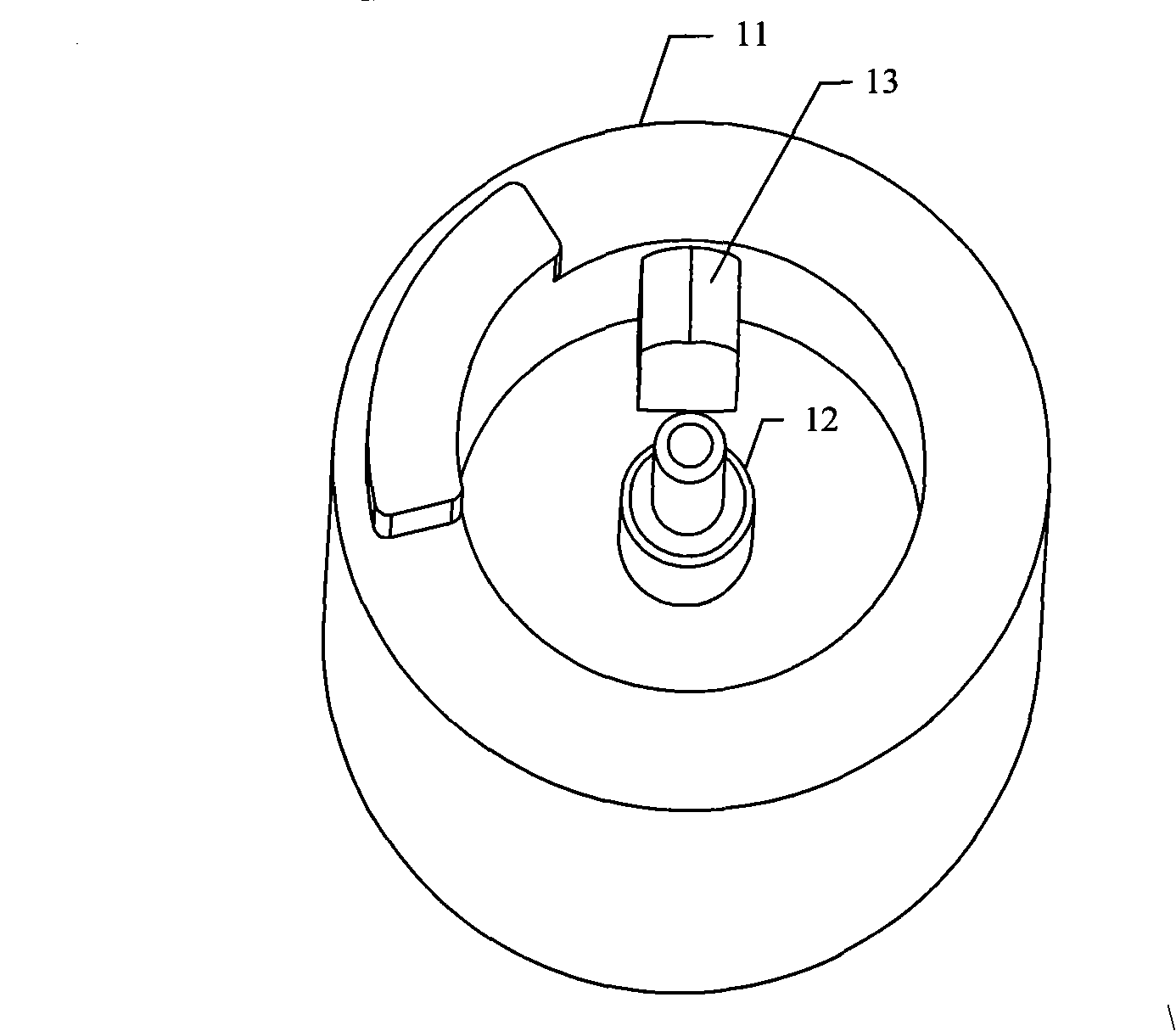
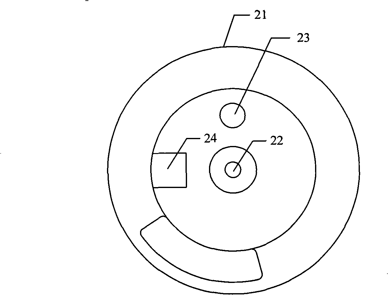
[0019] figure 2 It is a three-dimensional structural schematic diagram of a magnetic rotor structure of the present invention. image 3 It is a top view of a magnetic rotor structure of the present invention. Figure 4 It is a side sectional view of a magnetic rotor structure of the present invention. combine figure 2 , image 3 with Figure 4 As shown, the magnetic rotor structure of...


PUM


Abstract

The invention provides a magnetic rotor structure and a power-driven switching valve, wherein the power-driven switching valve comprises a magnetic rotor structure, a valve seat, a slide block, and an outer cover sleeve of the power-driven switching valve; the magnetic rotor structure comprises a magnetic rotor, a shaft and a key; one end of the shaft is arranged in a valve seat bottom hole of the valve seat; the key is used for clamping with a key groove of the slide block; the outer cover sleeve of the power-driven switching valve is sleeved on the valve seat, wherein the distance between the magnetic rotor and the inner wall of the outer cover of the power-driven switching valve is 0.2mm-1.0mm. According to the technical scheme provided by the invention, through the arrangement of the distance of 0.2mm-1.0mm between the magnetic rotor and the inner wall of the outer cover of the power-driven switching valve, and through the arrangement of at least one through hole which is arranged on the magnetic rotor and is communicated with the upper part and the lower part of the magnetic rotor, the technical defect that the normal valve opening of the power-driven switching valve is influenced because of the pressure difference of a medium existing between the upper part and the lower part of the magnetic rotor in the prior art is overcome.

Description

technical field [0001] The invention relates to the field of refrigeration engineering, in particular to a magnetic rotor structure and an electric switching valve. Background technique [0002] In the prior art, referring to Chinese patent CN101270826A, this patent application relates to an electric switching valve, which includes a magnetic rotor structure, and as figure 1 It is shown in the three-dimensional structural diagram of the magnetic rotor structure in the prior art, the magnetic rotor structure includes the magnetic rotor 11, the shaft 12 and the key 13; in the practical application of the refrigeration cycle system, the medium flows in from the inlet to fill the entire valve body, The slider engaged on the magnetic rotor 11 through the key 13 rotates with the shaft 12, so that at least one outlet on the flat bottom surface of the valve seat is opened, due to the magnetic rotor 11 and the inner wall of the electric switching valve housing of the electric switchi...

Claims


Application Information

Patent Timeline
IPC IPC(8): F16K11/074F16K31/02
Inventor 丁帅锋舒小辉
Owner ZHEJIANG SANHUA CO LTD
Why Eureka
Try Eureka