Closed synchronous control hydraulic system and four-way shuttle

A hydraulic system and synchronous control technology, which is applied in the field of warehousing and logistics, can solve problems such as low efficiency, low control accuracy, and low stability, and achieve the effects of avoiding rebound, ensuring synchronization, and improving synchronization

Active Publication Date: 2022-04-01
SHANGHAI SURAY INFORMATION TECH CO LTD
View PDF6 Cites 0 Cited by
  • Summary
  • Abstract
  • Description
  • Claims
  • Application Information

AI Technical Summary

Problems solved by technology

In the former, multiple pumps input the same flow to each hydraulic cylinder, and the output flow of the pump is controlled by changing the displacement of the pump, thereby adjusting the movement speed of the actuator. The pump control system has high efficiency and less energy loss, but due to the hydraulic pressure The response speed of the pump is not high, the dynamic characteristics of the pump control system are relatively poor, and the control accuracy is not high
The latter refers to controlling the speed of the actuator by controlling the opening of the valve port of the hydraulic valve (proportional valve, servo valve, etc.). Natural frequency, good dynamic characteristics, but because part of the oil output by the pump flows back to the oil tank through the relief valve, the system efficiency is low and the system heat is high
[0004] At present, there is no good method to improve the synchronization accuracy at home and abroad. Most of them use the method of correcting the error loop to avoid the accumulated error caused by multiple reciprocating movements, but this is only from the quality of the system components or the structure of the oil circuit. , low stability and low efficiency

Method used


Image

  • Closed synchronous control hydraulic system and four-way shuttle
  • Closed synchronous control hydraulic system and four-way shuttle
  • Closed synchronous control hydraulic system and four-way shuttle

Examples


Embodiment Construction

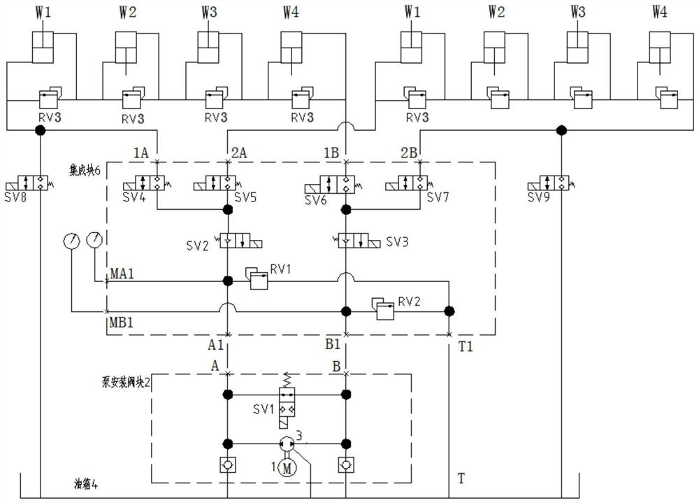
[0038] In order to make the object, technical solution and advantages of the present invention clearer, the present invention will be described in further detail below in conjunction with the embodiments and accompanying drawings. Here, the exemplary embodiments and descriptions of the present invention are used to explain the present invention, but not to limit the present invention.

[0039] Here, it should also be noted that, in order to avoid obscuring the present invention due to unnecessary details, only the structures and / or processing steps closely related to the solution according to the present invention are shown in the drawings, and the related Other details are not relevant to the invention. It should be emphasized that the term "comprising / comprising" when used herein refers to the presence of a feature, element, step or component, but does not exclude the presence or addition of one or more other features, elements, steps or components.

[0040] Here, it should...


PUM


Abstract

The invention provides a closed synchronous control hydraulic system and a four-way shuttle, including: a hydraulic pump, the hydraulic pump includes a first oil outlet / oil inlet interface and a second oil outlet / oil inlet interface; a first hydraulic cylinder group and a second oil outlet interface; Two hydraulic cylinder groups, the first hydraulic cylinder group and the second hydraulic cylinder group both include two or more synchronously operating hydraulic cylinders, and the hydraulic cylinders in the same hydraulic cylinder group are connected in series; the oil inlet end of each hydraulic cylinder The oil circuit of the oil return end is also connected through the oil circuit with a relief valve; the first main oil circuit connected with the first oil outlet / inlet interface of the hydraulic pump; the second oil outlet / inlet interface of the hydraulic pump The second main oil circuit connected; the fifth oil circuit connecting the first oil circuit or the third oil circuit and the fuel tank; the sixth oil circuit connecting the second oil circuit or the fourth oil circuit and the fuel tank; the fifth Pressure relief valves are respectively provided on the oil circuit and the sixth oil circuit. The hydraulic system includes pressure relief valves and overflow valves for automatic oil replenishment to each hydraulic cylinder, improving the synchronization of the multi-cylinder system.

Description

technical field [0001] The invention relates to the field of warehousing and logistics, in particular to a closed synchronous control hydraulic system and a four-way shuttle. Background technique [0002] At present, there are many realization forms of the hydraulic synchronization system, and its basic form can be divided into open-loop control mode and closed-loop control mode. Accuracy to control the synchronization of actuators. Generally speaking, the hydraulic synchronization system adopting the open-loop control method has a simple structure and low cost, but because there is no feedback compensation, it cannot eliminate errors caused by different loads, differences in the manufacturing accuracy of hydraulic cylinders, and hydraulic oil leakage. [0003] In addition, the hydraulic system can also be divided into two types: pump-controlled synchronous control and valve-controlled synchronous control. In the former, multiple pumps input the same flow to each hydraulic...

Claims


Application Information

Patent Timeline
Patent Type & Authority Patents(China)
IPC IPC(8): F15B11/22F15B13/08F15B13/02F15B20/00F15B21/044F15B21/041B66F9/075B66F9/22
CPCF15B11/22F15B13/0807F15B13/027F15B20/007F15B21/044F15B21/041B66F9/07586B66F9/22F15B2211/20546
Inventor 许庆波罗强李英德
Owner SHANGHAI SURAY INFORMATION TECH CO LTD
Why Eureka
Try Eureka