Booster Hydraulics

A hydraulic device and hydraulic technology, applied in the direction of fluid pressure actuators, fluid pressure converters, servo motor components, etc., to achieve the effect of control, compact structure, and smooth switching

Active Publication Date: 2017-08-04
蚌埠尚维知识产权运营有限公司
View PDF8 Cites 0 Cited by
  • Summary
  • Abstract
  • Description
  • Claims
  • Application Information

AI Technical Summary

Problems solved by technology

However, there is currently no hydraulic device that can meet the above requirements

Method used


Image

  • Booster Hydraulics

Examples


Embodiment Construction

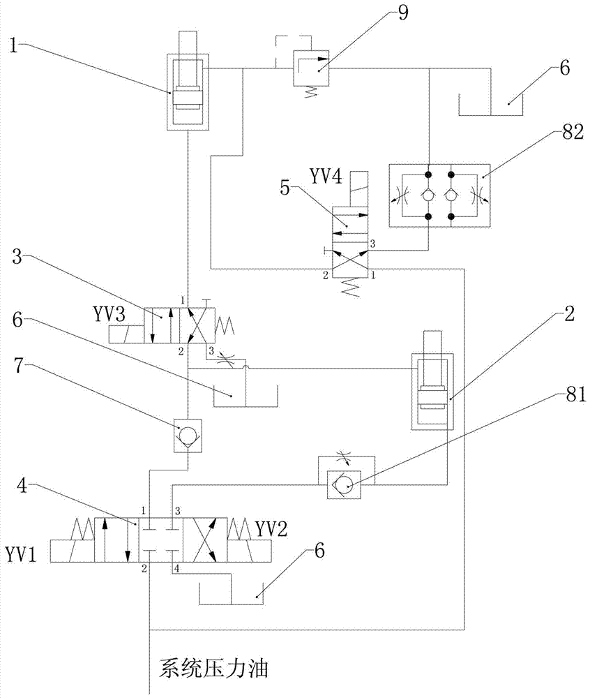
[0018] like figure 1 As shown, the pressurized hydraulic device of the present invention is mainly composed of a power cylinder 1, a pressurized cylinder 2, a first electromagnetic reversing valve 3, a second electromagnetic reversing valve 4, a third electromagnetic reversing valve 5, an oil return Pool 6, one-way valve 7, first one-way throttle valve 81, second one-way throttle valve 82 and safety valve 9.

[0019] The power cylinder 1 is the ejection cylinder of the cooking utensil forming press, and is arranged on the base of the press. The rod cavity of the power cylinder is connected with the oil return tank 6, and the safety valve 9 is connected in series on the connecting pipeline.

[0020] The first electromagnetic reversing valve 3 is a two-position four-way electromagnetic reversing valve, its first oil port is connected to the rodless chamber of the power cylinder 1, and its second oil port is connected to the rod chamber of the booster cylinder 2 ; Its third oil...


PUM


Abstract

The invention discloses a pressurized hydraulic device. It includes a power cylinder and a hydraulic control assembly connected to the power cylinder, and is characterized in that the hydraulic control assembly is mainly composed of a booster cylinder, a first electromagnetic reversing valve, a second electromagnetic reversing valve and a third electromagnetic reversing valve , the first oil port of the first electromagnetic reversing valve is connected to the rodless chamber of the power cylinder, and the second oil port is connected to the rod chamber of the booster cylinder; the second electromagnetic reversing valve The first oil port is connected to the second oil port of the first electromagnetic reversing valve, the second oil port is connected to the system pressure oil circuit, and the third oil port is connected to the rodless chamber of the booster cylinder ; The first oil port of the third electromagnetic reversing valve is connected to the system pressure oil circuit, and the second oil port is connected to the rod chamber of the power cylinder. The invention has a compact structure, can realize linkage between two oil cylinders, and can increase the hydraulic pressure of the power oil cylinder when necessary.

Description

technical field [0001] The invention belongs to the technical field of hydraulic control, and in particular relates to a hydraulic device mainly used to realize pressurization of an ejection cylinder of a cooking utensil forming press. Background technique [0002] At present, in the cooking utensil molding press, the ejection oil cylinder is arranged on the base of the press machine, and the cooking utensils are ejected after the cooking utensils are pressed. However, some manufacturers hope to double the pressure of the ejector cylinder so that it can be used as a blank holder cylinder after the mold is reversed. Therefore, the ejection oil circuit of the cookware forming press only provides system pressure when the ejection cylinder is used as the ejector device, and when the ejection cylinder is used as the edge cylinder, the ejection oil circuit is high-pressure to double the ejection pressure. . However, there is currently no hydraulic device that can meet the above ...

Claims


Application Information

Patent Timeline
Patent Type & Authority Patents(China)
IPC IPC(8): F15B3/00F15B13/02
Inventor 陈伟俊
Owner 蚌埠尚维知识产权运营有限公司
Why Eureka
Try Eureka