
Balanced valve element structure and regulating valve

A balanced and regulating valve technology, applied in the field of regulating valves, can solve the problems of large pressure difference between the front and rear of the minimum flow regulating valve, prone to fracture at the stressed place, and reduced service life of the valve core, so as to avoid fracture, damage and risk of fracture The effect of reducing and prolonging the service life

Pending Publication Date: 2022-01-21
SHANGHAI POWER EQUIP RES INST
View PDF4 Cites 0 Cited by
  • Summary
  • Abstract
  • Description
  • Claims
  • Application Information

AI Technical Summary

Problems solved by technology

Due to the large pressure difference between the front and rear of the minimum flow regulating valve, after the high-temperature and high-pressure differential medium passes through the throttling elements such as the labyrinth disc or sleeve, even if the pressure is reduced, there is still a certain amount of erosion on the valve core, resulting in damage to the valve core
Moreover, when the valve needs to be opened and closed, due to the influence of the large pressure difference between the front and rear, the actuator needs to output a large torque to move the valve core, and the force on the valve core is prone to breakage, which greatly reduces the service life of the valve core.

Method used


Image

  • Balanced valve element structure and regulating valve
  • Balanced valve element structure and regulating valve
  • Balanced valve element structure and regulating valve

Examples


Embodiment Construction

[0037] The technical solutions of the present invention will be further described below in conjunction with the accompanying drawings and embodiments. It should be understood that the specific embodiments described here are only used to explain the present invention, but not to limit the present invention. In addition, it should be noted that, for the convenience of description, only the parts related to the present invention are shown in the drawings but not all of them.

[0038] In the description of the present invention, it should be noted that unless otherwise specified and limited, the terms "installation", "connection" and "connection" should be understood in a broad sense, for example, it can be a fixed connection or a detachable connection. Connection; it can be a mechanical connection or an electrical connection; it can be a direct connection or an indirect connection through an intermediary, and it can be the internal communication of two components. Those of ordin...


PUM


Abstract

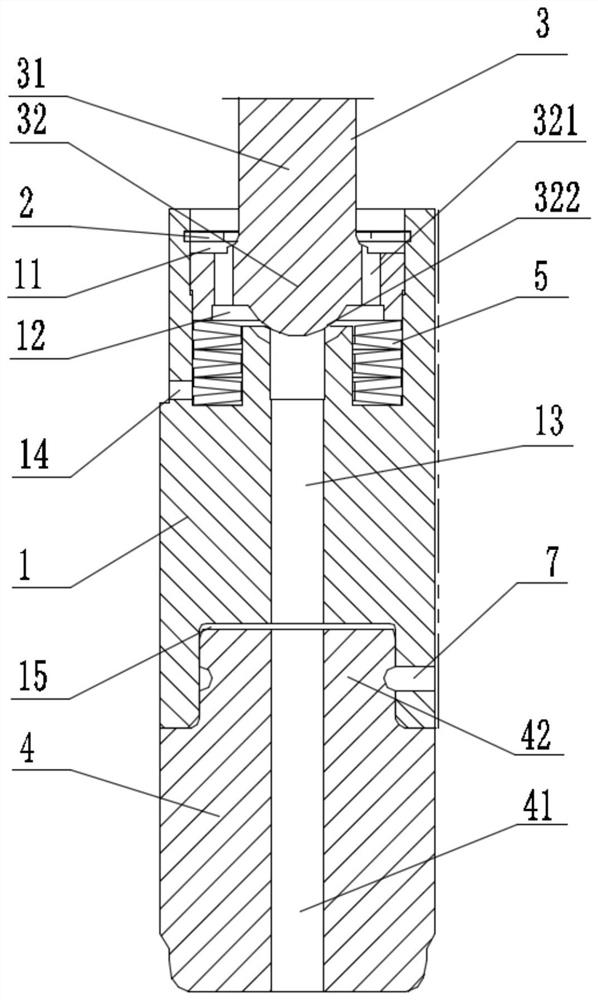
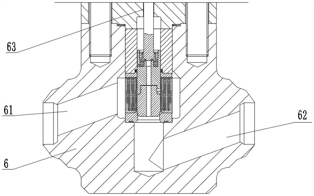
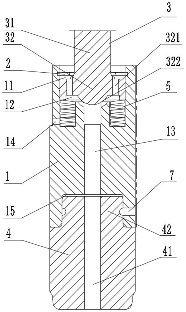
The invention relates to a balanced valve element structure, which comprises an upper valve element, a check ring, a valve rod and a lower valve element; a first groove is arranged at the upper end of the upper valve element, a containing groove is annularly arranged on the side wall of the first groove, the outer ring of the check ring is clamped in the containing groove, and a first cavity is formed by the first groove and the check ring; a first through hole is axially arranged at the bottom of the first groove in a penetrating manner; the valve rod comprises a first part and a second part, and the first part penetrates through the inner ring of the check ring; the second part is arranged in the first cavity and divides the first cavity into a first upper cavity and a first lower cavity; a second through hole is arranged on the second part of the valve rod in a penetrating mode and communicated with the first upper cavity and the first lower cavity; the valve rod can move downwards relative to the upper valve element to block an upper end opening of the first through hole and can also move upwards relative to the upper valve element to open the upper end opening of the first through hole, so that the first through hole is communicated with the first lower cavity; and the lower valve element is connected to the lower end of the upper valve element, a third through hole is axially arranged on the lower valve element in a penetrating mode, and the third through hole is communicated with the first through hole.

Description

technical field [0001] The invention relates to the technical field of regulating valves, in particular to a balanced valve core structure and a regulating valve. Background technique [0002] In the field of industrial automation process control, the regulating valve is used to receive the control signal output by the regulating control unit, and to change the flow, pressure, temperature, liquid level and other process parameters of the medium with the help of power operation, which is a commonly used control element. Due to the large pressure difference between the front and rear of the minimum flow regulating valve, after the high-temperature and high-pressure differential medium passes through the throttling elements such as the labyrinth disc or sleeve, even if the pressure is reduced, there is still a certain amount of erosion on the valve core, resulting in damage to the valve core. Moreover, when the valve needs to be opened and closed, due to the influence of the la...

Claims


Application Information

Patent Timeline
IPC IPC(8): F16K1/36F16K1/48F16K39/02F16K47/00F16K47/02
CPCF16K1/36F16K1/482F16K39/022F16K47/00F16K47/023
Inventor 周蔷李连翠龚胜泉贾俊阳张含吴英明
Owner SHANGHAI POWER EQUIP RES INST
Learn More