Laser ablation sampling system

A sample introduction system and laser ablation technology, which are used in the preparation of test samples, material analysis by electromagnetic means, instruments, etc., can solve problems such as gas path effects, and achieve the effect of avoiding leakage

Active Publication Date: 2018-12-21
MATERIAL INST OF CHINA ACADEMY OF ENG PHYSICS
View PDF7 Cites 0 Cited by
  • Summary
  • Abstract
  • Description
  • Claims
  • Application Information

AI Technical Summary

Problems solved by technology

[0003] However, in the existing laser ablation sampling system, the sample chamber can only accommodate a small amount of samples at a time
During the operation, the sample chamber needs to be opened frequently to replace the sample, which easily affects the gas path in the laser ablation sampling system

Method used


Image

  • Laser ablation sampling system
  • Laser ablation sampling system
  • Laser ablation sampling system

Examples


Embodiment 1

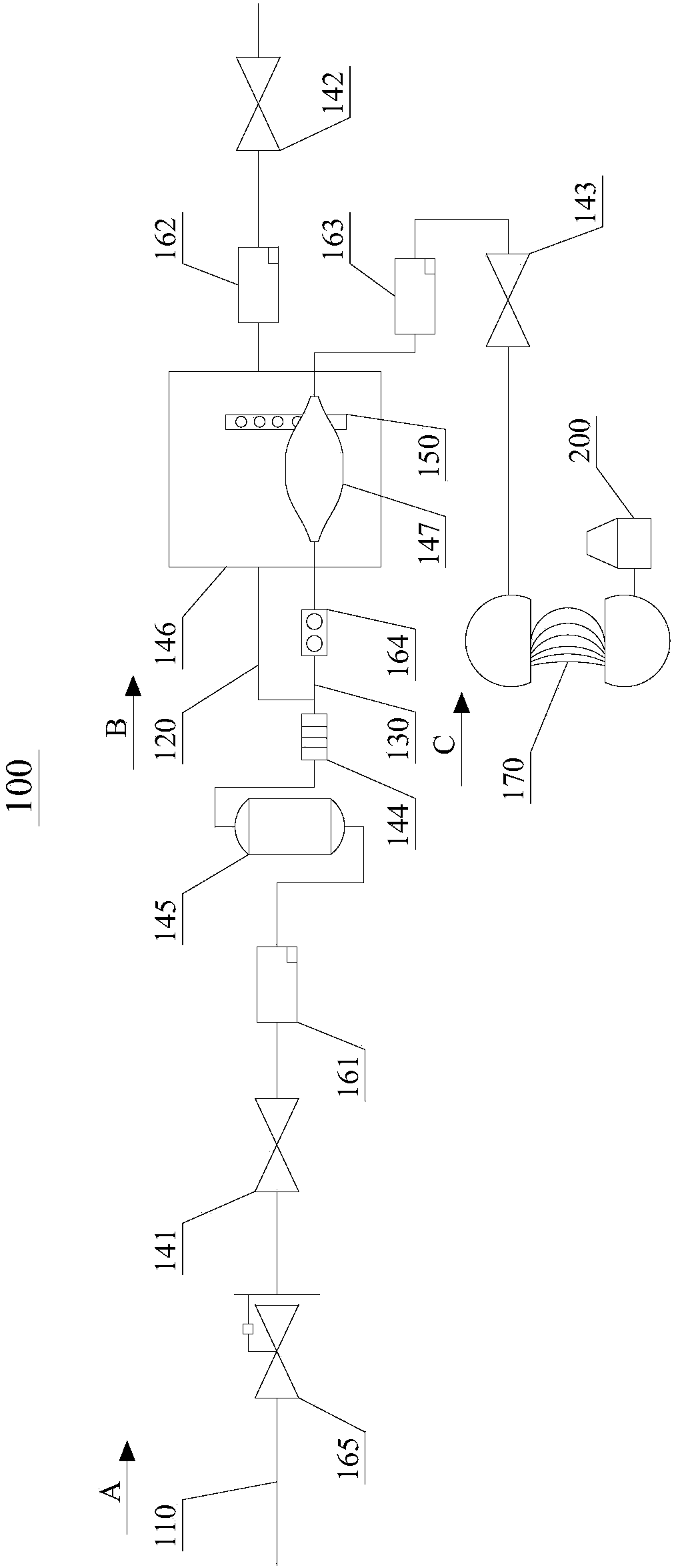
[0037] refer to figure 1 , figure 1 It is a schematic structural diagram of a laser ablation sample introduction system 100 in an embodiment of the present invention. The laser ablation sampling system 100 includes a main pipeline 110 , a first branch pipeline 120 and a second branch pipeline 130 . The main pipe 110 has a beginning and an end. During operation, the gas flows from the beginning of the main pipe 110 to the end of the main pipe 110, that is, the gas flows figure 1 Flow in the direction of A. The first branch pipeline 120 also has a beginning and an end, and the beginning of the first branch pipeline 120 is connected to the end of the main pipeline 110 . The gas flowing out from the end of the main pipeline 110 enters the first branch pipeline 120, and flows from the beginning of the first branch pipeline 120 to the end of the first branch pipeline 120, that is, the gas is figure 1Flow in the B direction. The second branch pipeline 130 also has a start end an...

Embodiment 2

[0065] refer to Figure 4 , Figure 4 It is another structural schematic diagram of the laser ablation sample introduction system 100 in the embodiment of the present invention. This embodiment also provides a laser ablation sample introduction system 100, which adds a vacuum pump 180 and a three-way valve 190 on the basis of Embodiment 1.

[0066] The three-way valve 190 has a first port 191 , a second port 192 and a third port 193 . The third interface 193 is connected to the end of the second branch pipeline 130 , and the first interface 191 is connected to the vacuum pump 180 .

[0067] The working process is as follows:

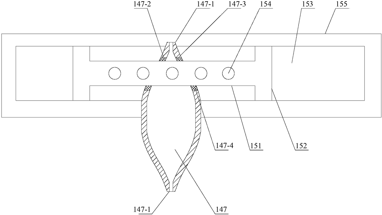
[0068] A plurality of samples are fixed on the sample holder bar 151 , and the samples are evenly arranged in the length direction of the sample holder bar 151 .

[0069] Close the second on-off valve 142 , the third on-off valve 143 and the fourth on-off valve 144 , and open the first on-off valve 141 . Carrier gas (inert gas, such as helium) is fe...


PUM


Abstract

The invention discloses a laser ablation sampling system, which comprises a first on-off valve, a buffer tank and a fourth on-off valve which are sequentially arranged in the main pipeline from the beginning to the end; The outer chamber and the second on-off valve in the branch pipeline; it also includes a sample chamber and a third on-off valve arranged in the second branch pipeline in sequence from the beginning to the end; the sample chamber is located in the outer chamber; the sample chamber is provided with Relative sample inlet and sample outlet; also includes a sample delivery device arranged in the outer chamber, the sample delivery device includes a sample holder that slidably passes through the sample chamber through the injection inlet and the sample outlet, and is connected with the sample holder And it is used to drive the driving device that the sample support bar slides on the straight line where the sample inlet and the sample outlet are located. The invention realizes the automatic replacement of samples without frequently opening the sample chamber, thus avoiding the influence of frequent opening of the sample chamber on the gas path in the laser ablation sample feeding system.

Description

technical field [0001] The invention relates to the technical field of inorganic element and isotope analysis and testing, in particular to a pretreatment system for inductively coupled plasma mass spectrometry, and in particular to a laser ablation sample introduction system. Background technique [0002] As a new in-situ sampling technology, laser ablation can be used in conjunction with various analytical instruments such as inductively coupled plasma mass spectrometry. Laser ablation can effectively avoid the problems of sample destruction caused by traditional wet digestion sample preparation, tedious and time-consuming sample preparation, loss of volatile analytes, and polyatomic ion interference caused by water and acid in the digestion solution. [0003] However, in the existing laser ablation sampling system, the sample chamber can only accommodate a small amount of samples at a time. During the operation, the sample chamber needs to be opened frequently to replace...

Claims


Application Information

Patent Timeline
Patent Type & Authority Patents(China)
IPC IPC(8): G01N1/44G01N35/10G01N27/62G01N27/626
CPCG01N1/44G01N27/62G01N35/10
Inventor 文明何康昊宋江锋姚勇杨雷邓立李佩龙
Owner MATERIAL INST OF CHINA ACADEMY OF ENG PHYSICS
Why Eureka
Try Eureka