
Continuous measurement method and device for force measuring wheel set

The technology of a force measuring wheel set and a measuring method, which is applied in the direction of measuring devices, measuring force, instruments, etc., can solve the problems of vertical force measurement sensitivity changes, complexity, and less effective information, and achieve the minimum quantity and low measurement cost , Decoupling the effect of simple calculation process

Active Publication Date: 2011-07-06
LOCOMOTIVE & CAR RES INST OF CHINA ACAD OF RAILWAY SCI
View PDF0 Cites 15 Cited by
  • Summary
  • Abstract
  • Description
  • Claims
  • Application Information

AI Technical Summary

Problems solved by technology

The disadvantage of the discontinuous measurement method is that the amount of effective information is small, there are many error links, and the data cannot be analyzed in the time domain or frequency domain, etc.
[0005] The disadvantage of the above-mentioned prior art of continuous measurement is that there are too many measurement bridges used in the existing continuous measurement method, for example, in some prior art, 4 measurement bridges are required for vertical force, and 2 measurement bridges are required for lateral force. measuring bridge
In addition, due to the lateral movement of the wheel-rail contact point during the rotation of the wheel, the sensitivity of the vertical force measurement changes, so it must also be equipped with 4 special bridges for position measurement
Or, in order to adopt different measurement sensitivity coefficients according to different rotation angle positions, it is necessary to have a synchronous and accurate measurement of the angle of rotation of the force-measuring wheel set, thus causing a very complicated process in the decoupling calculation of effective output and interference output, and also Reduced measurement accuracy

Method used


Image

  • Continuous measurement method and device for force measuring wheel set
  • Continuous measurement method and device for force measuring wheel set
  • Continuous measurement method and device for force measuring wheel set

Examples


Embodiment Construction

[0039] The technical solutions in the embodiments of the present invention will be clearly and completely described below in conjunction with the accompanying drawings in the embodiments of the present invention. Obviously, the described embodiments are only some specific embodiments of the present invention, not all embodiments. Based on the embodiments of the present invention, all other embodiments obtained by persons of ordinary skill in the art without creative efforts fall within the protection scope of the present invention.

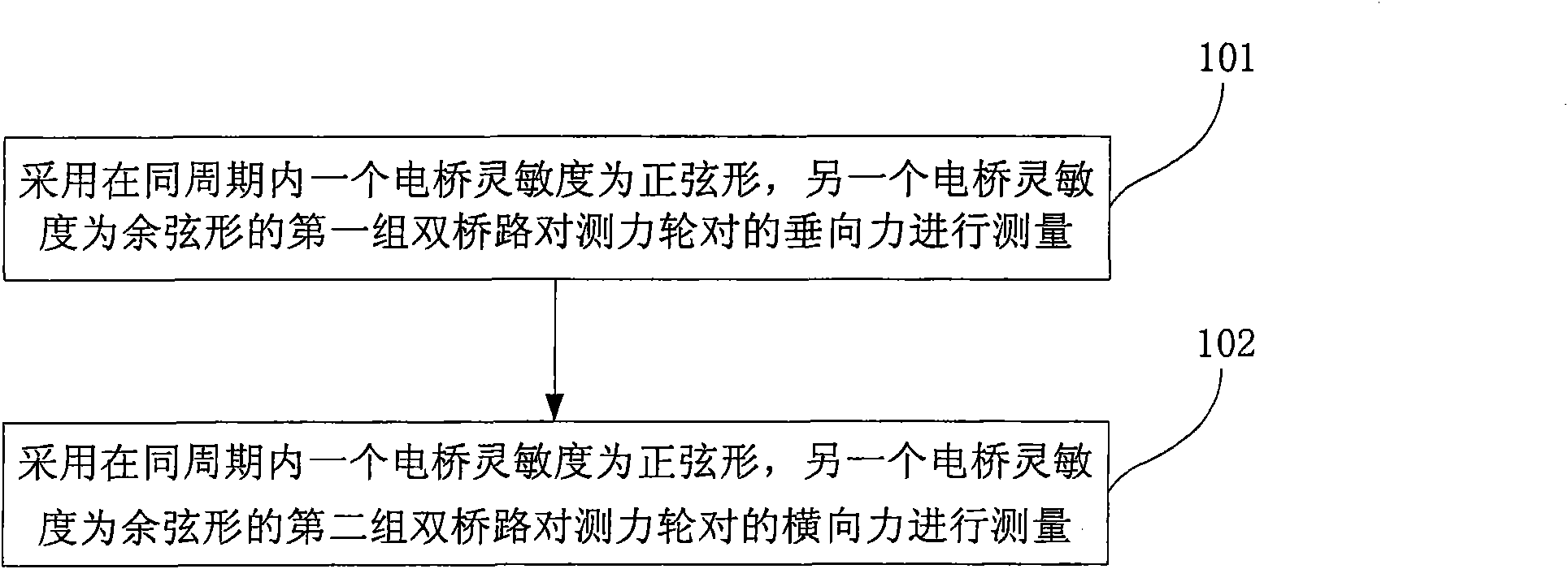
[0040] like figure 1 Shown is a flow chart of a continuous measurement method for a force-measuring wheel set according to an embodiment of the present invention.

[0041] Including step 101, the vertical force of the force measuring wheel set is measured by using the first group of double bridge circuits in which the sensitivity of one measuring bridge is sinusoidal and the sensitivity of the other measuring bridge is cosine in the same cycle;

...


PUM


Abstract

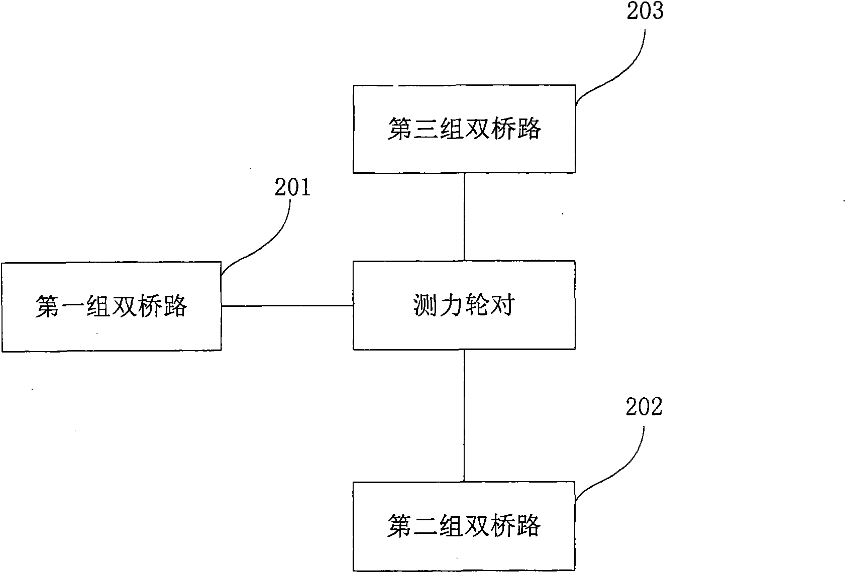
The invention relates to the field of measurement of wheel-rail force of railway locomotive vehicles, provides a novel continuous measurement method and a novel continuous measurement device for a force measuring wheel set, and aims to solve the problems of complex measurement method of the force measuring wheel set, low measurement accuracy and the like existing in the prior art. The method comprises the following steps of: measuring vertical force of wheel-rail by using a first group of double bridge circuits; and measuring transverse force of the wheel-rail by using a second group of double bridge circuits, wherein the sensitivity of a measuring bridge is sinusoidal and the sensitivity of the other measuring bridge is cosinusoidal in the same period in the first group of double bridge circuits; and the sensitivity of a measuring bridge is sinusoidal and the sensitivity of the other measuring bridge is cosinusoidal in the same period in the second group of double bridge circuits. The embodiment of the invention has the advantages that: since the vertical force and the transverse force are measured by a double-bridge circuit measurement means of the same period, and are superposed and synthesized, measuring sensitivity in an entire wheel circumference range of rotation of a wheel can be kept constant and is irrelative to rotation angle of the force measuring wheel set; and the measurement is more accurate.

Description

technical field [0001] The invention relates to the field of wheel-rail force measurement of locomotives, in particular to a continuous measurement method and device for a force-measuring wheel set. Background technique [0002] Wheel-rail force measurement is a basic work in the railway industry, which is related to whether the rolling stock can run safely on the track line, and has always been valued by countries all over the world. [0003] In the past, most force-measuring wheel sets used the discontinuous measurement method, which is characterized in that two or more effective detection signals can be obtained within the range of one rotation of the wheel, but there are invalid signals between each effective signal. The disadvantage of the discontinuous measurement method is that the amount of effective information is small, there are many error links, and the data cannot be analyzed in the time domain or frequency domain. [0004] With the advancement of science and t...

Claims


Application Information

Patent Timeline
Patent Type & Authority Applications(China)
IPC IPC(8): G01L1/22
Inventor 李谷祖宏林储高峰胡爱全焦文孙浩清俞展猷王希玲赵永智章润鸿
Owner LOCOMOTIVE & CAR RES INST OF CHINA ACAD OF RAILWAY SCI
Learn More